NanoVNA Test Fixture
Continuing from the last post for the NanoVNA Test Board, this post completes the assembly of the parts into a ready to use test fixture.
Recap: The fixture was procured unassembled in December 2025, but it was too cold out in the garage to put together since then. Recent spring-thaw here in Chicagoland finally allowed temperatures out there to reach into the low 60's F. Wanted to get this done as Winter2 is certain to arrive soon!
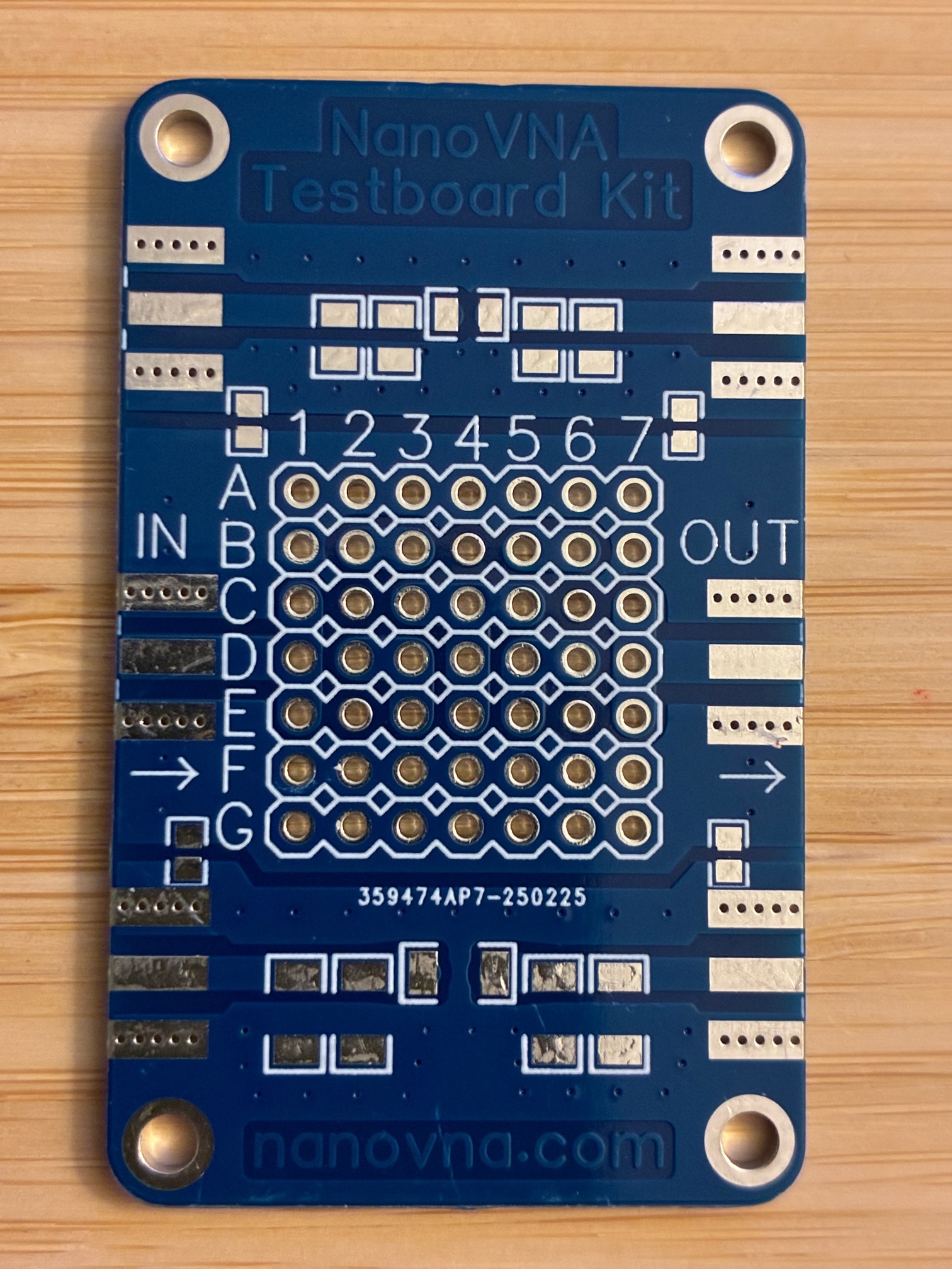
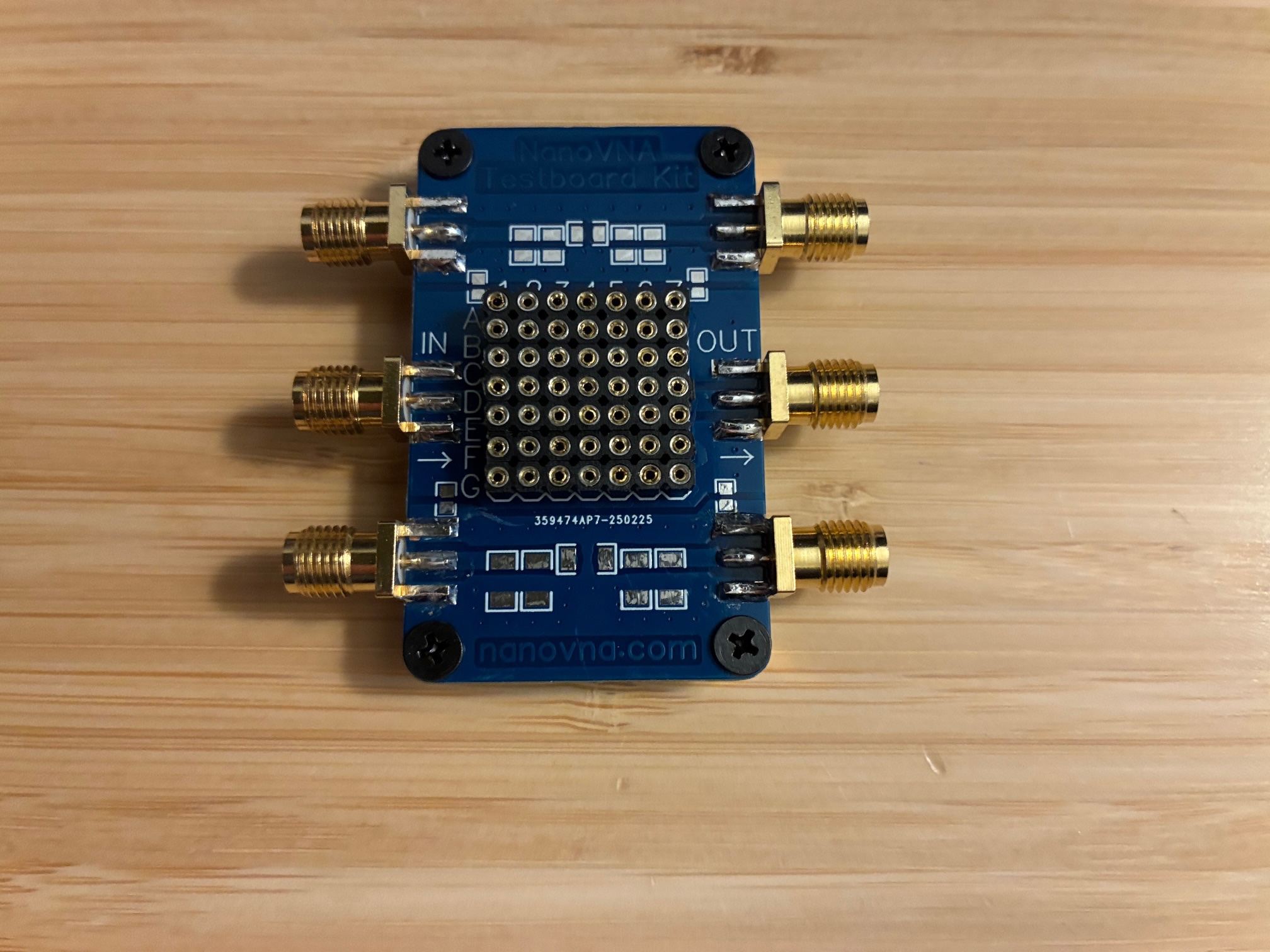
The board connects two SMA ports in the middle portion with a socket array supporting insertion of leaded components, and development/test of various types of electronics/RF circuits in that path. The extra pin sockets supplied allows soldering surface mount components onto a pair of pins, and thereafter, use in the fixture. Below is the bare board as supplied.
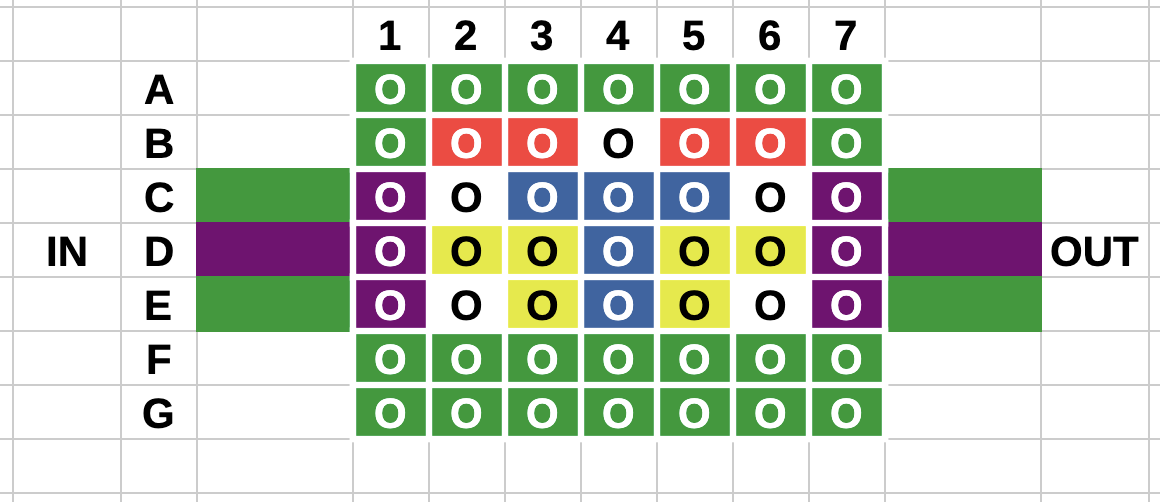
I used my DMM to ohm out the connections for the pin-grid array yielding these connections. Same colors are connected together. (White color pins are isolated from other white pins.)
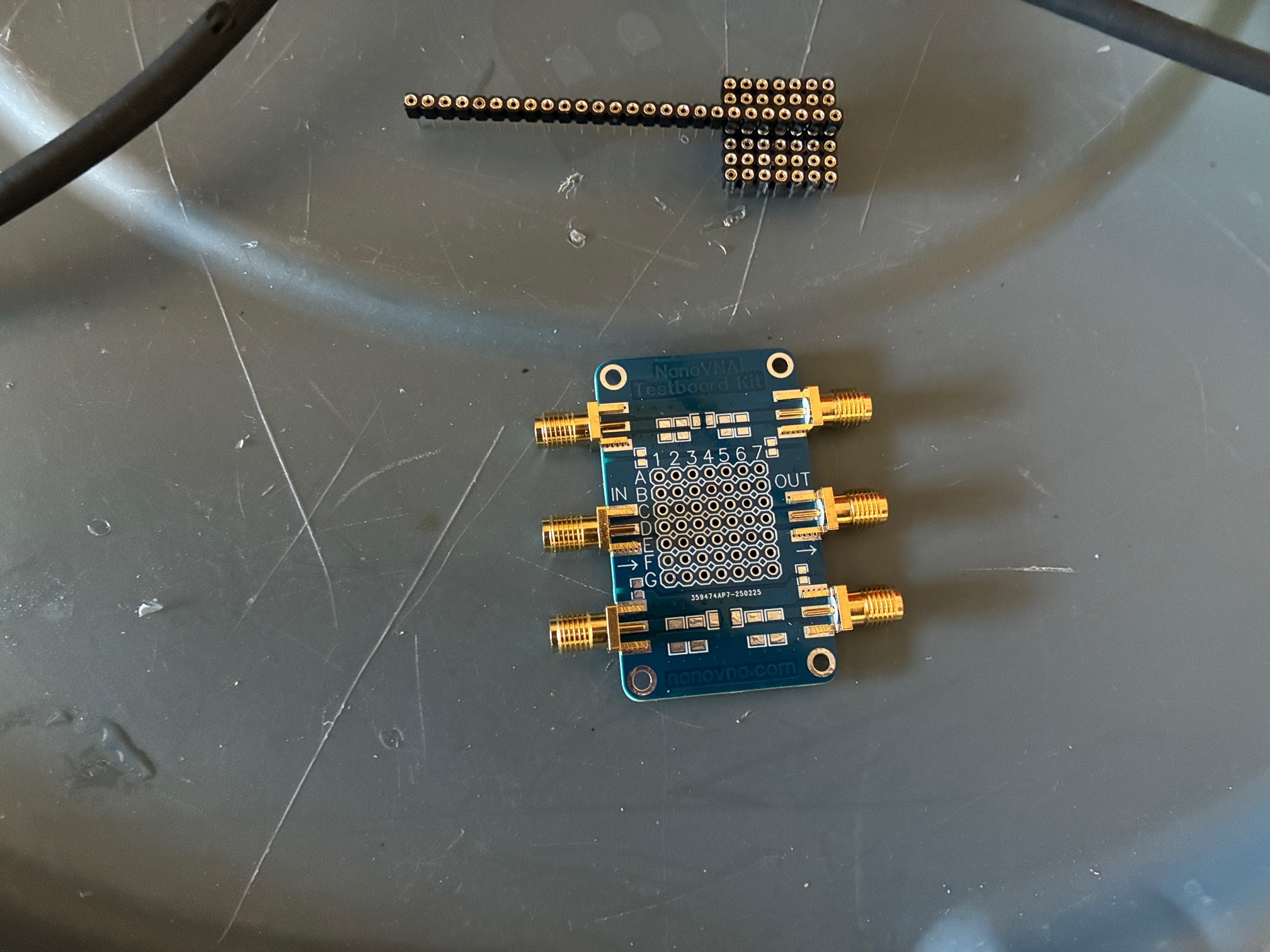
I started assembly with a dry fit of all components into the board. The SMA jack ground connections were loose and were squeezed together slightly with pliers to give a snug fit to the ground pads. Keeping the jacks firmly in place during soldering helped speed things along out in the 60F garage.
The pin grid array of sockets was held temporarily together with the left over strip of pins. (Saw this on an internet video and copied to keep the sockets lined up during assembly.)
Definitely solder the SMA jacks before the array of sockets. Getting the iron in and making good physical contact during soldering (ground pin and pad on board) was a little challenging for some of the connections.
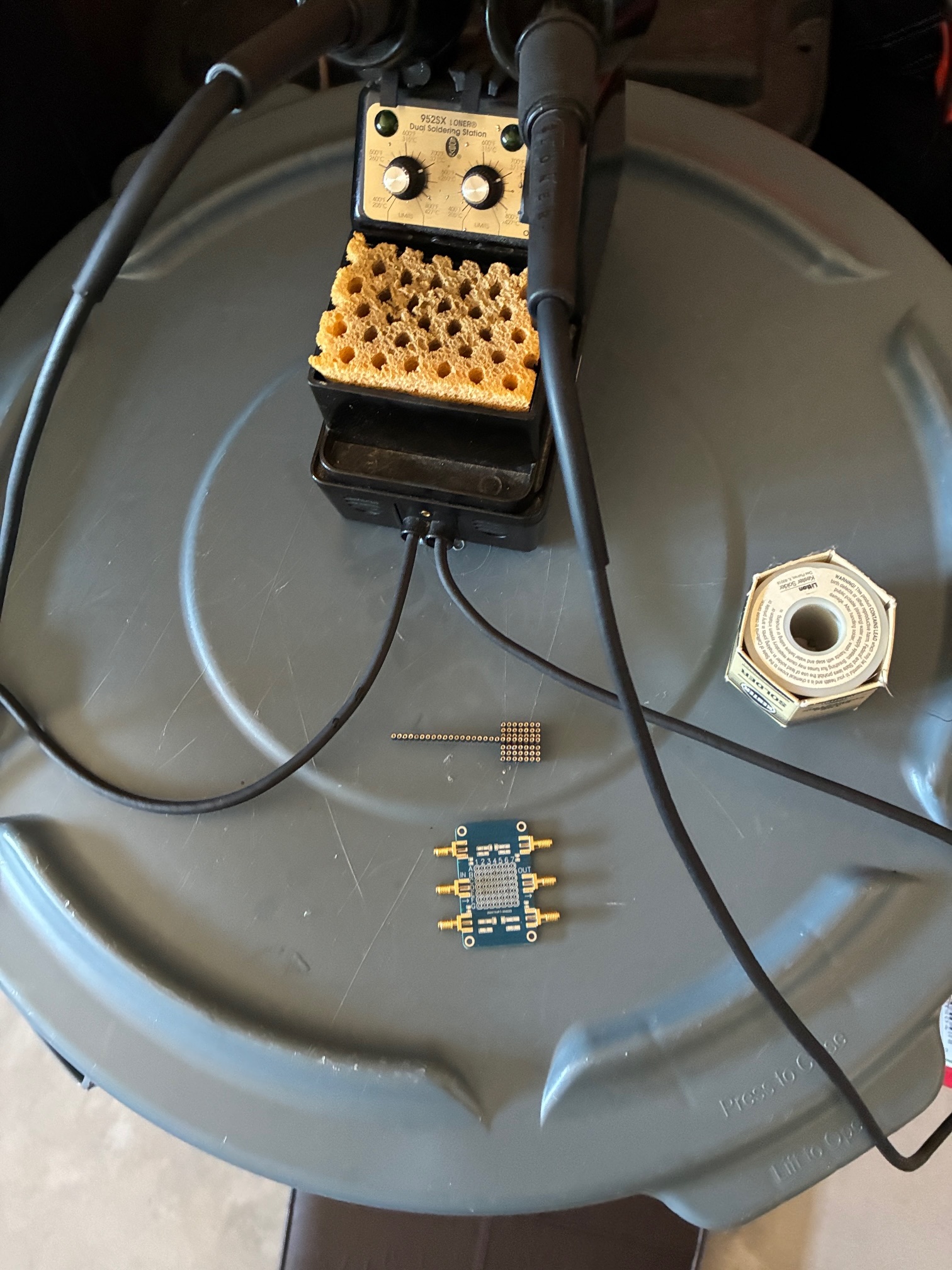
I used the larger wedge-tip iron of the Loner 952SX soldering iron for all connections today. The smaller round tip did not allow enough contact area and heat level to even work on the pin-socket connections. The larger tip worked fine for both SMA jacks and the pin-grid array sockets.
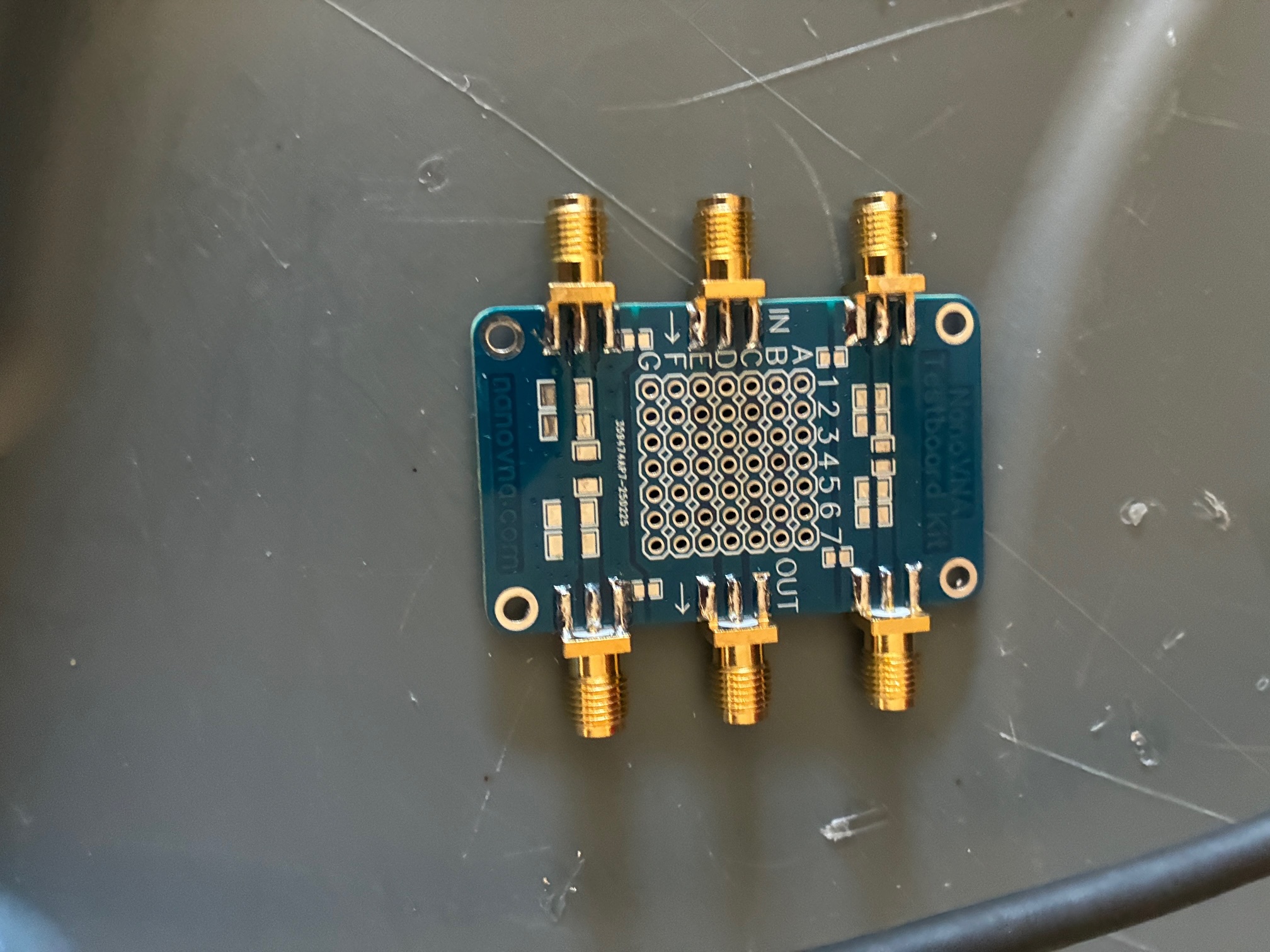
The SMA jacks are soldered on both sides (above). Soldering the corner pins of the socket array helped keep it in place while soldering the other 45 connections (below).
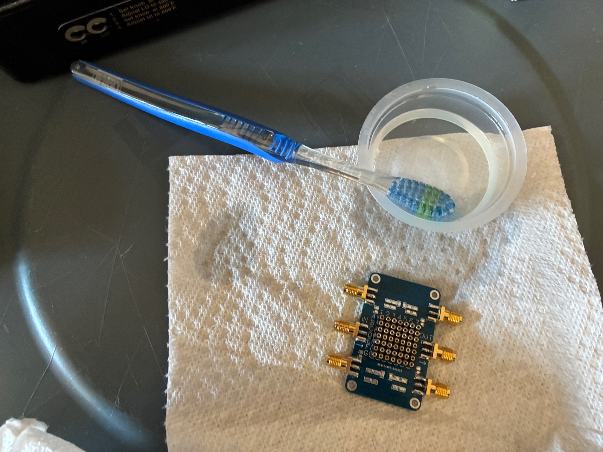
With all connections completed, it was time to clean the flux from the solder joints. I used some 70% Isopropyl Alcohol (IPA) and an old tooth brush - liberally applying the cleaner and having it drip off the board onto the paper towel below.
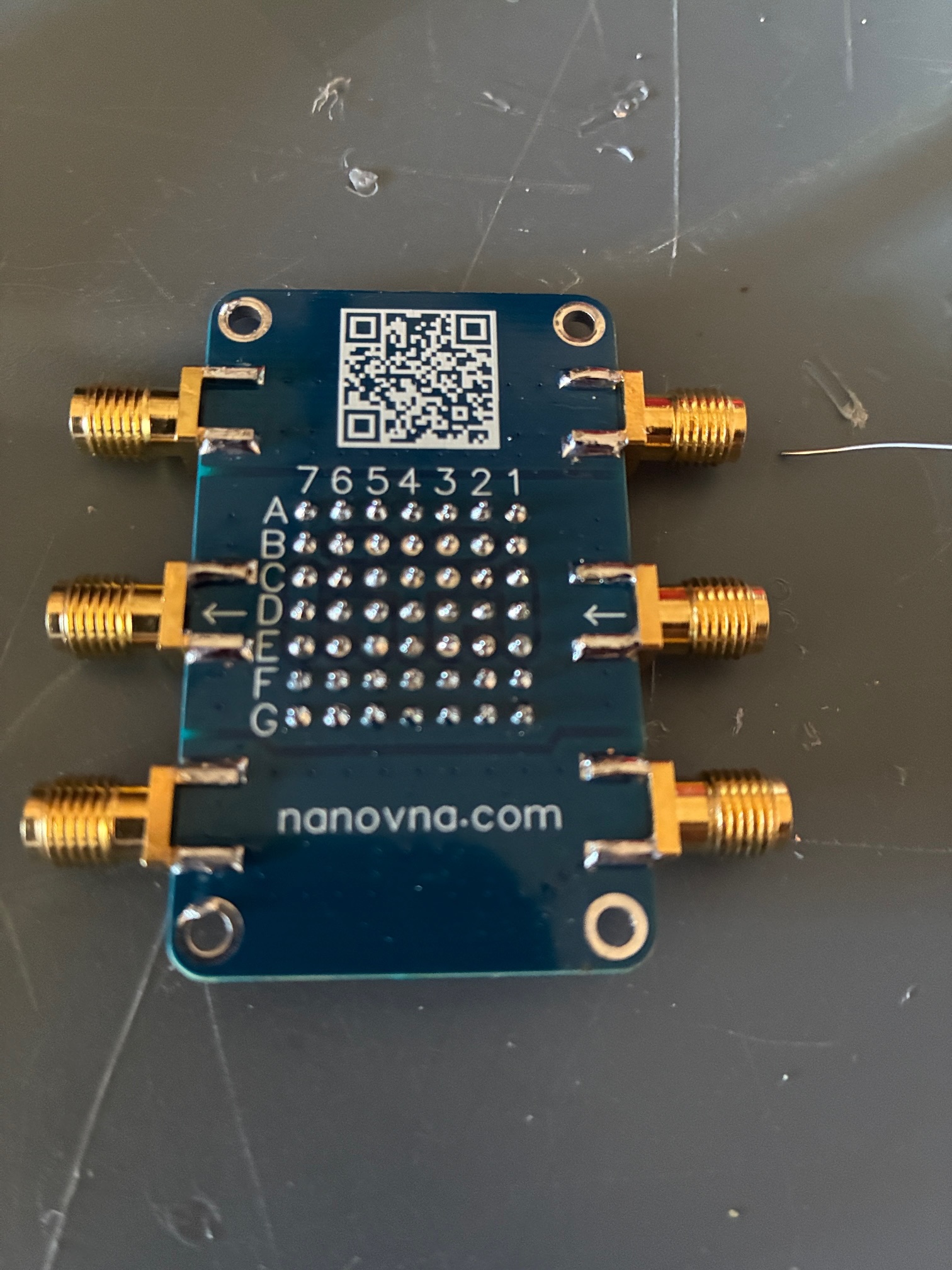
For the bottom-side photo above, note that there is some excess solder onto the lower left mounting hole. This was trimmed off with an X-ACTO knife before installing the supplied "feet" for the fixture. The photo below shows the four stand-off mounting feet installed onto the board.
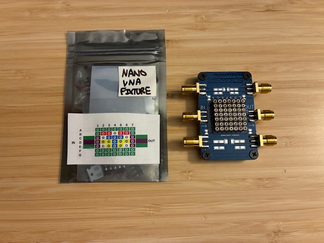
This fixture is likely going to live inside the NanoVNA-H4 pouch accessories pocket. The extra pin-sockets and the two supplied 50 Ohm SMT resistors are inside the small ESD bag so they won't get lost or separated from the fixture. I taped a copy of the connections guide sheet to the ESD bag as a reminder of what connects to what.
The NanoVNA test fixture is completed and ready for future use. I also plan to use this fixture with my TinyGTC and experiment with input protection circuits in the weeks ahead. Achievement Unlocked: NanoVNA test fixture assembled!
More fun ahead - Now with coax breakout to/from 49 socket pins!
All author photos taken with an iPhone 16e.