Pluto + RTL-SDR & SATSAGEN
Have been using ADALM Pluto SDR with Alberto IU1KVL's SATSAGEN software and wondered if there was benefit to using an RTL-SDR receiver with a Pluto SDR transmitter for S21 (through) measurements. This post sets up these two SDR's in the software and makes a few measurements to see how well they work together.
SATSAGEN Software Setup
Capturing the configuration for two SDR's in the system is slightly different than only using one SDR. With SATSAGEN started, but not yet powered up, select the Toolbar check box along the bottom middle of the window.
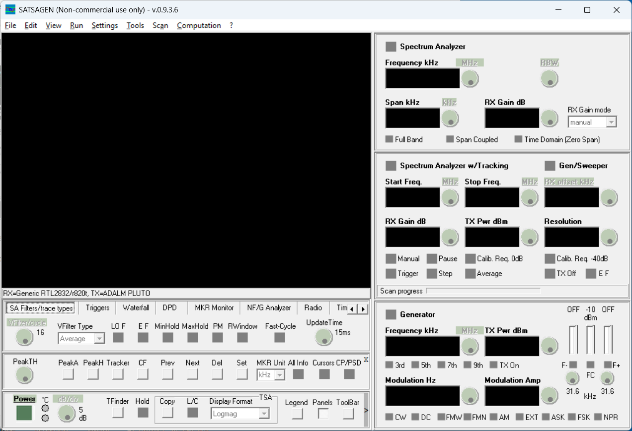
This shows the tool bar and makes the Settings button visible.
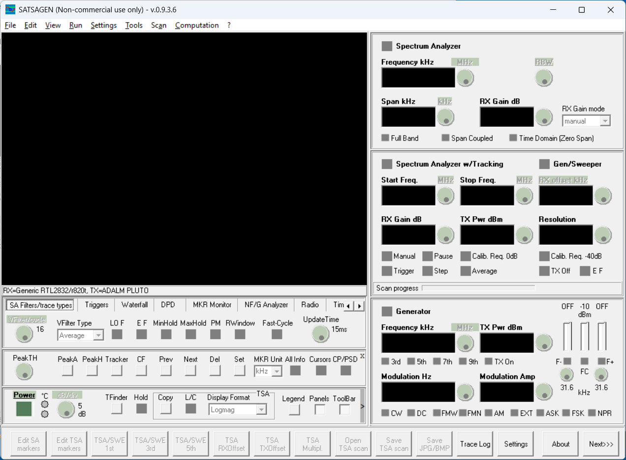
Pressing the Settings button brings up a new window with multiple tabs along the top.
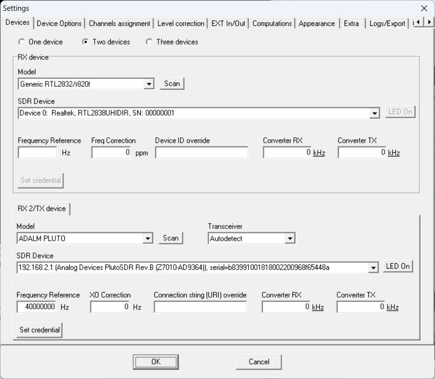
Staying on the Devices tab, set the RX device in the upper sub-window and TX device (or second RX device) in the lower window as shown above.
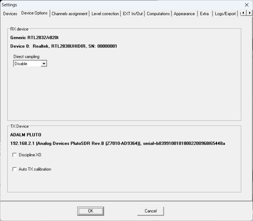
Click on the Device Options tab to set any additional configurations needed. Note that Discipline XO was left unchecked. (This might better have been enabled, as it supports "tied together" frequency alignment between the RX and TX SDR during system operation.)
System Checkout and Calibration
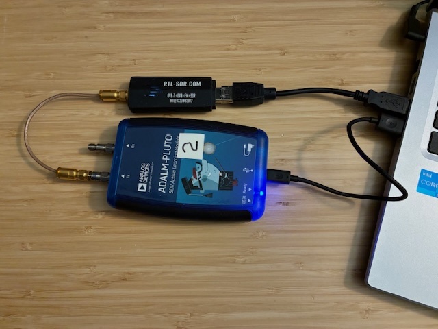
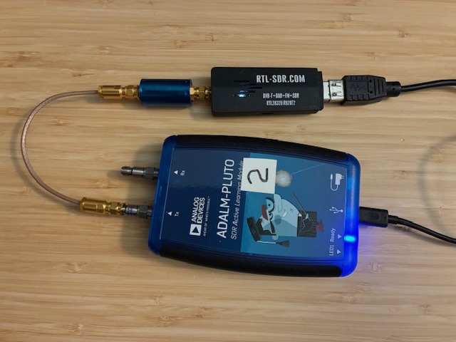
With both devices configured, let's check to see if they both agree reasonably closely on a loop back test. Pluto TX is connected to the RTL-SDR RX SMA with a short cable.
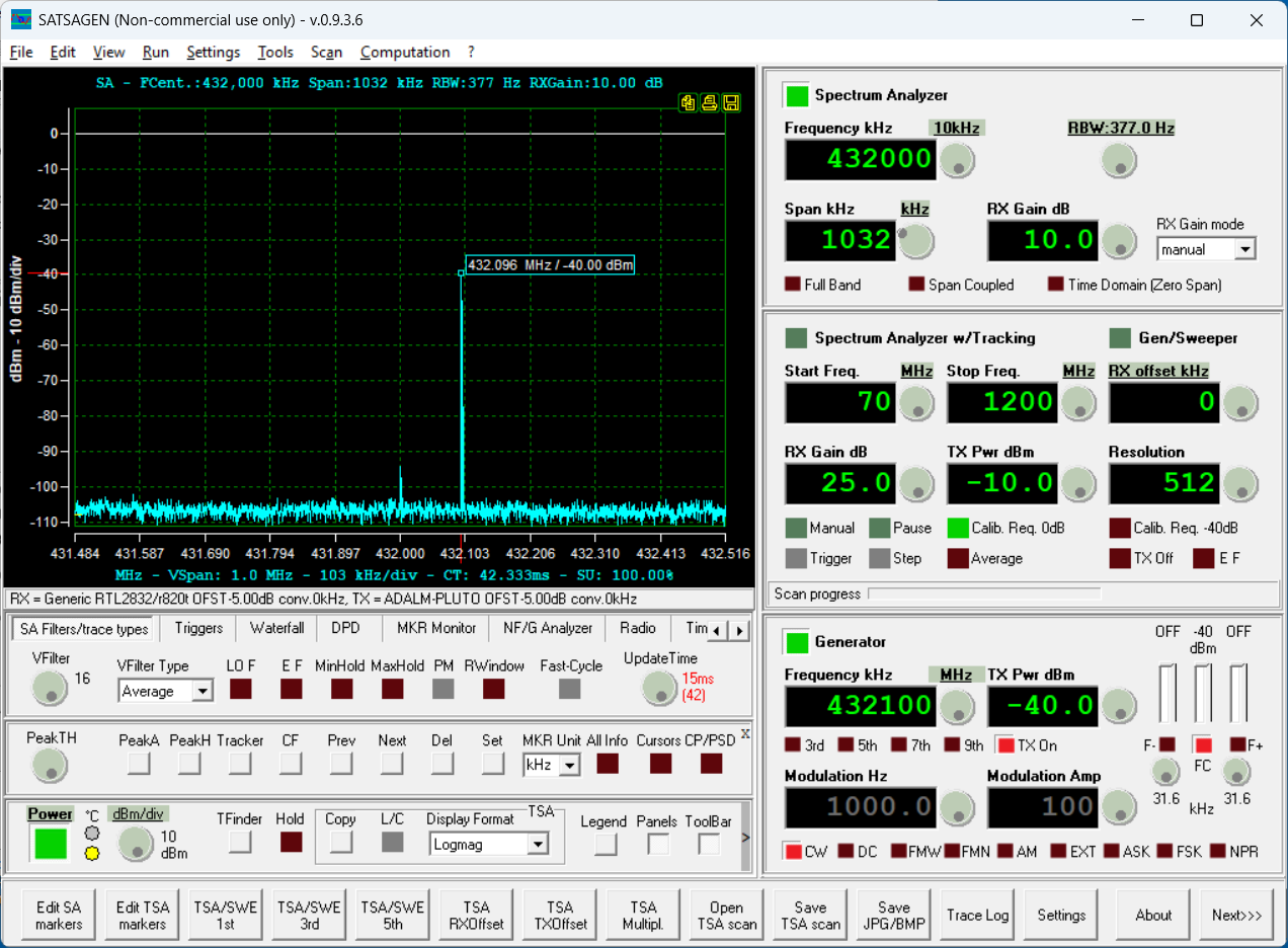
With SATSAGEN powered up, and Generator and Spectrum Analyzer (SA) enabled, the screen capture below shows that the 432.1 MHz -40 dBm test signal is received at -40 dBm by the SA.
The next steps will use the Spectrum Analyzer w/Tracking (SA/T) function to perform a sweep over set RF frequencies and measure the S21 path loss/gain parameter. First we perform a loop-back calibration using a straight through RF cable. Then we can add devices to see how the system performs. (Only passive RF filters are measured in today's tests. Hope to be able to measure a few RF amplifiers in the future.)
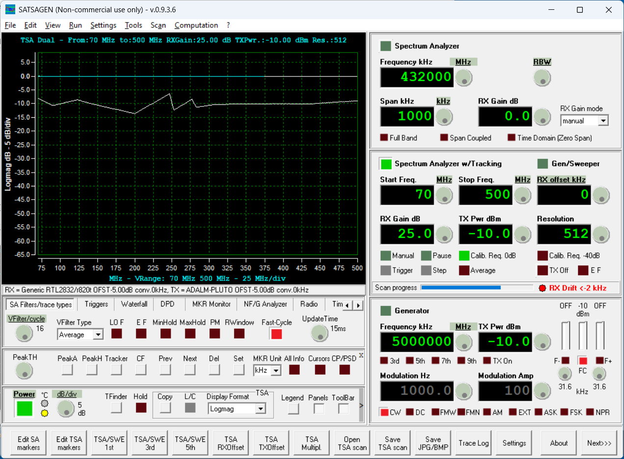
See above for a picture of the Pluto TX port connected to the RTL-SDR receive port SMA. Enabling the SA/T function yields this uncalibrated response. There are two lines in the screen shot. A horizontal line at 0 dB (partially blue and white in this capture). This is the reference line and where we want our calibrated measurement to measure after we complete that process. The second line below at about -10 dB is the uncorrected response. (Note that this screen shot was captured in-process and shows a green check box for Calb. Req 0 dB in the SA/T box on the right. This is normally starts out being red in color indicating uncorrected measurements, and turns green once calibration is completed.)
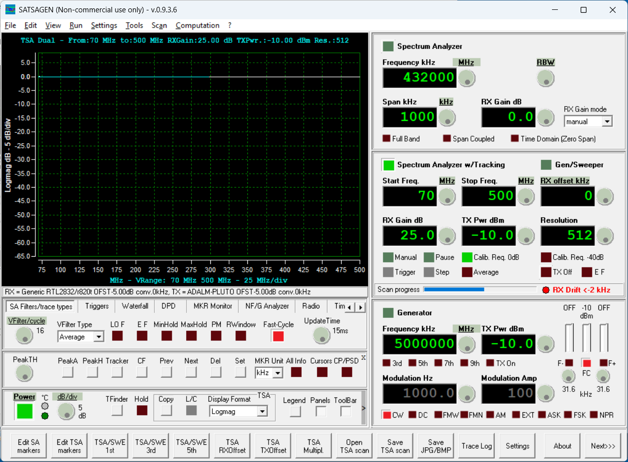
Once the level is calibrated with the loop back cable, the measurement trace is very close to the 0 dB line (and we can see the trace progressing along the white 0 dB reference line in the capture below). There is also an indication of the drift or frequency separation between the RX and TX SDR signals shown in the lower right portion of the SA/T sub-window. Will need to see how this changes when the Discipline XO check box is checked over on the Device Options tab in the Settings window.
Realized after this calibration that the frequency start and stop points didn't align with the series of RF filters that I wanted to test. Changed frequencies and calibrated the system again to cover 70 to 1200 MHz...
System Use Measuring RF Filters
Let's measure a few coaxial SMA-connectorized Mini-Circuits filters. These just connect in-line to the existing RF cable setup. The blue device is a typical filter using for these tests.
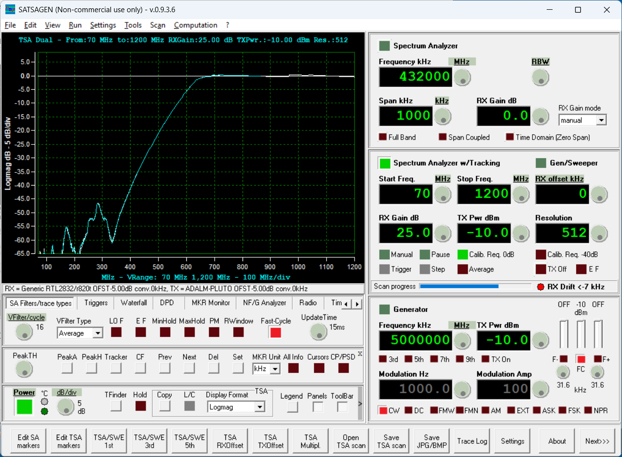
Here is the response of a Mini-Circuits SHP-200 (200 MHz high pass filter).

Below is the response of a Mini-Circuits SHP-900 (900 MHz high pass filter).
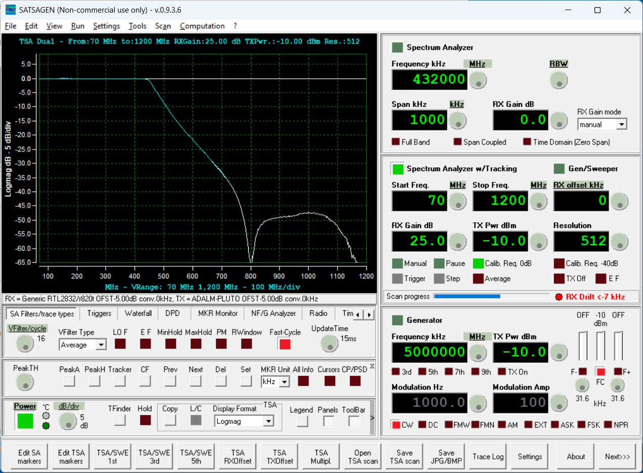
Below is the response of a Mini-Circuits SLP-300 (300 MHz low pass filter).
The above filters were all SMA connectorized filters with good RF shielding and input/output port isolation. Pass band insertion loss was low and stop band rejection appearing to meet manufacturer's specifications.
I also had a modular Mini-Circuits PLP-100 RF filter installed onto a chunk of proto-board with reasonably short traces to SMA jacks. This single-sided hand-carved traces board did not have good isolation and did not provide rejection levels expected to be able to achieve with a good layout RF filter circuit (expecting to see > 50 dB rejection above 200 MHz in the stop band).
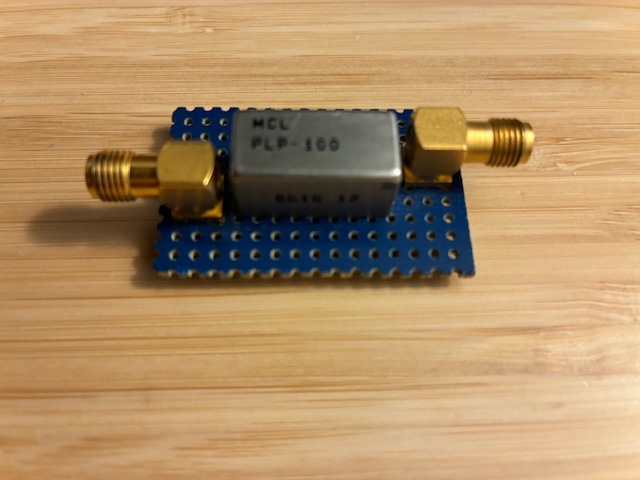
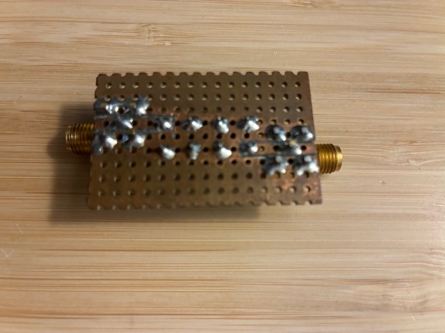
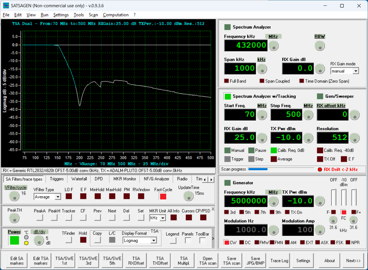
At RF frequencies, layout counts!
Summary
Today's tests showed that an RTL-SDR can be used as a receiver with SATSAGEN using a Pluto SDR as the transmit source. Performance was good for this configuration and will consider using the RTL-SDR in the future with the standard Pluto SDR's.
There a limitation with the RTL-SDR's upper frequency response only going up to about 1.5 GHz, but there is a potential benefit in using direct-sampling receive mode with this device for future lower-frequency measurements (under the 70 MHz lower limit of the Pluto SDR's).
Achievement Unlocked: Use a new/different SDR receiver with SATSAGEN!
All author photos taken with an iPhone 16e.