Si5351A Phase Noise
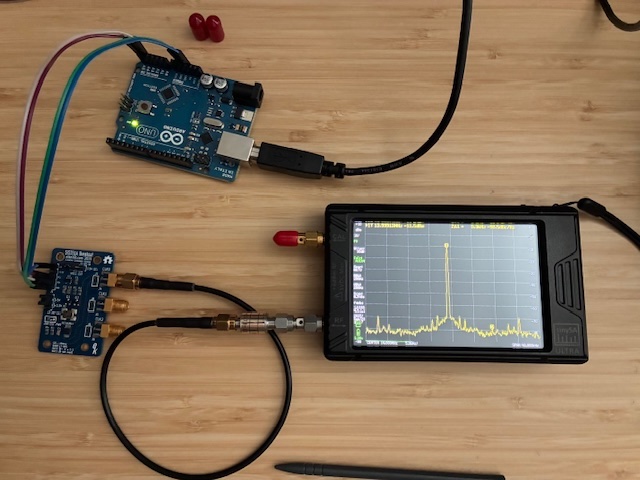
Examined the phase noise of the EtherKit Si5351A CLK0 output at 14 MHz using the Measurements - Phase Noise function on the TinySA-Ultra spectrum analyzer. These were quick measurements made without any significant power-on time stabilization.
The Si5351A setup was an Arduino UNO running the EtherKit demo code to program the eval board to output clocks on all three clock ports. Only the CLK0 port supplying 14 MHz was examined for this test. A 10 dB fixed SMA attenuator was used to reduce the ~ +3 dBm CLK0 output to under 0 dBm (per TinySA input level recommendations).
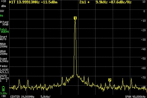
Measurements were made at 10 KHz and 1 KHz offsets from the 14.0 MHz clock output signal. Below is the 10 KHz offset plot that shows approximately -88 dB down at 10 KHz away from the main signal. There are some evident spikes in the spectrum with the offset marker appearing to be up on one above the noise level. No special efforts were made to minimize clock noise (just using what ever programming settings were in the demo code).
These spikes or discrete frequency spurs were not as evident in the 1 KHz offset spectrum plot. The noise level at 1 KHz offset was ~ 84 dB down from the carrier.
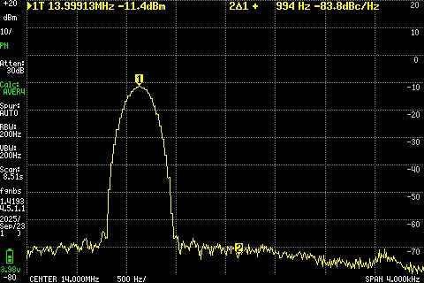
All in all, this looks very respectable for a $15 USD evaluation board.
Note for testing next time: Terminate all outputs to minimize reflections feeding back into the chip from unused OSC outputs.
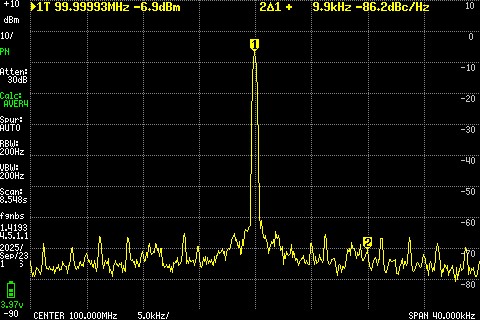
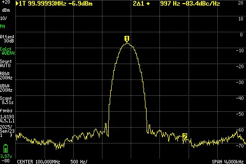
Next, a few similar measurements were made using my Wenzel Associates quartz oscillator which supplies ~ +13 dBm at 100 MHz. A 20 dB fixed SMA attenuator was used to get under 0 dBm for the TinySA RF input.

Below is the 10 KHz offset plot which shows approximately -86 dB down from the carrier. This plot also has some discrete spurious present including a little jog up in the noise level at around 8 KHz offset from the carrier. (This was not as prominent in the Si5351A at 10 KHz offset plot, but maybe there to some extent if we look closely?)
Looking at the 1 KHz offset spectrum shows a noise shape quite different from the Si5351A evaluation board, with the quartz oscillator noise falling off going away from the carrier, but then rising up again somewhat equally on both sides of the spectrum. The 1 KHz noise level is similar between the two signal sources. Probably want to look at these measurements a little closer in the future.
That's it for today's quick look at the Si5351A close-in (1 KHz and 10 KHz) phase noise levels. The good news is that it is not substantially different from my Wenzel test oscillator. Will continue creating an I2C control interface for the EtherKit Si5351A evaluation board and look at phase noise and other output signal parameters in the future. (Comparing phase noise at approximately the same test frequency, i.e., 100 MHz is a goal for ongoing tests.)
All author photos taken with an iPhone 16e. TinySA-Ultra screen shots were captured using the instrument's microSD card (press the little green SD symbol to capture a screen shot).