Examining RF Detectors with a Curve Tracer
Had a chance to setup the Digilent Analog Discovery 3 with the Transistor Tester (curve trace) adapter on a lark to see what the curves might look like for a few detectors retrieved from the small modular RF components case. Was not expecting much - mostly figuring how to connect them and expecting to see typical diode response curves.
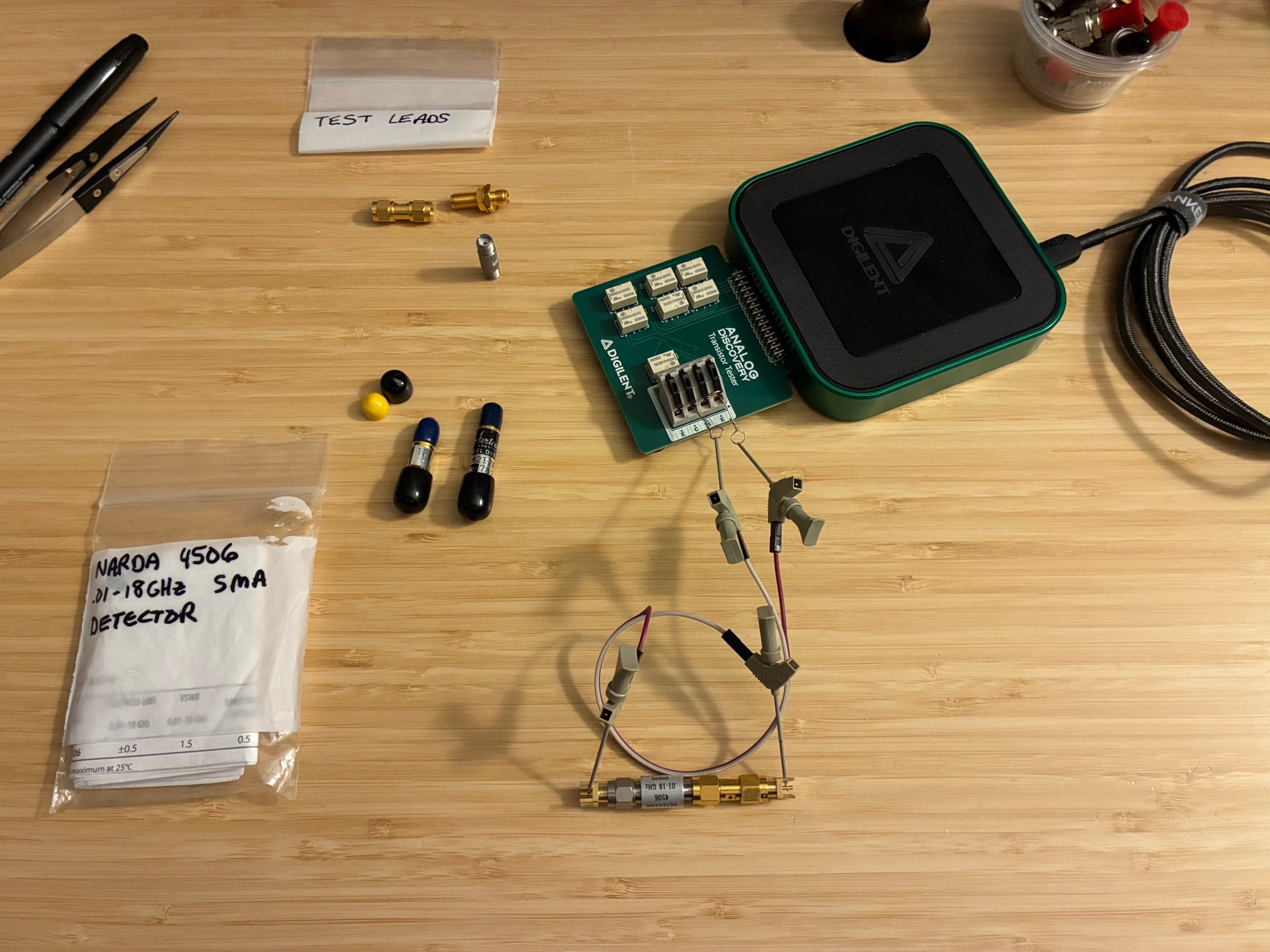
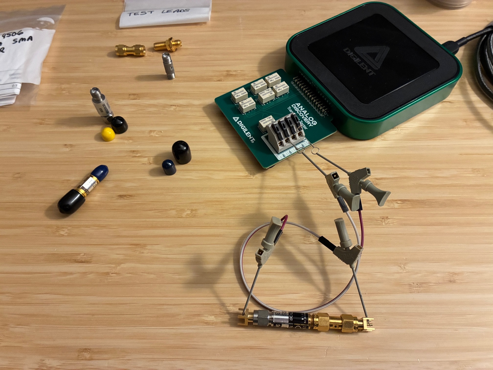
Started with a known good Narda 4506 .01-18 GHz SMA connector detector and worked through connecting it to the curve trace adapter using SMA jacks and some short jumpers. The photo below shows the AD3 with semiconductor test adapter, the Narda Ultra Broadband Schottky Detector, two SMA jacks, a SMA-M to SMA-M adapter, and the jumper clips to connect the diode to the test board. There are no connections to the SMA shield side, just the center pins are used for this test.
The Digilent Waveforms software has useful default settings and a connection guide at the upper right edge of the window. Below is the expected "it is a diode" curve obtained with this measurement. Note that the default Digilent semiconductor test for curve tracing is pretty limited (low currents and only plus/minus 5V available), but overall it is very useful to understand what is happening in the device under test. Also note that the software has many additional features including markers, additional curves, etc., that were not used here. Simple test only today...
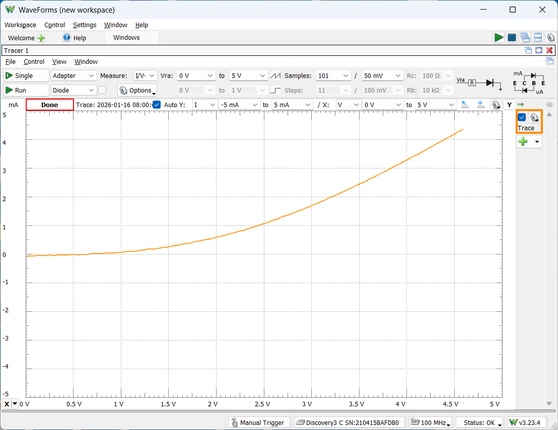
Note that the test autoscaled the Y-axis (mA) from zero to just over 4 mA as the applied voltage got close to the upper limit of 5V.
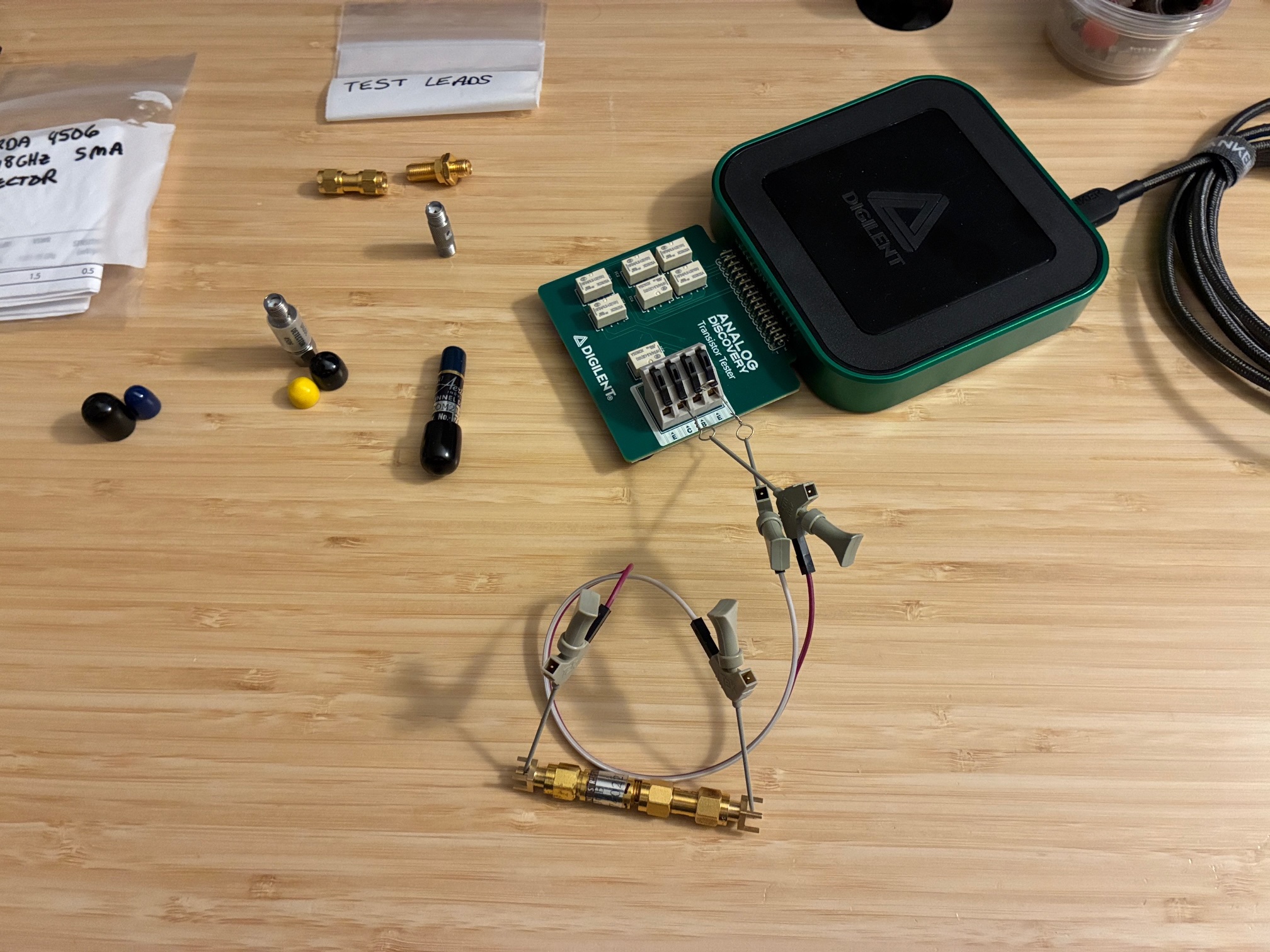
Next up was a known good AerTech Industries A9D006B Detector, SMA connectorized. I do not have a data sheet for this part. I found an old AerTech catalog over on the Internet Archive that had lots of information on their products but did not include this part or even a date for the catalog itself. Believe this was from the late 70's or early 80's based on an automated test photo in the catalog. Let's see what this curve looks like, and maybe if is approximately the same or different from the Narda curve above. The test setup is the same as for the Narda test.
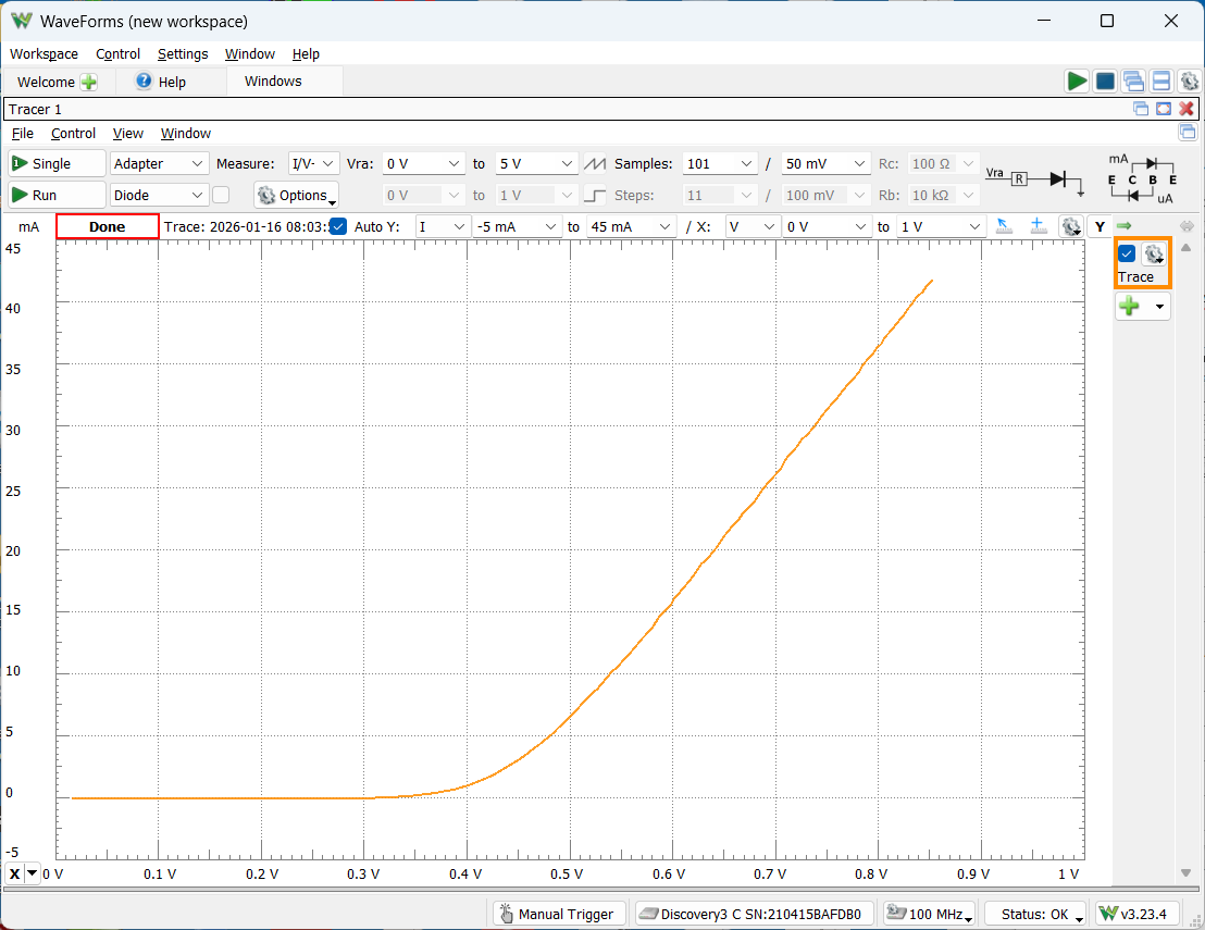
Sure enough, the detector displays a typical diode curve, but look at how the voltages and currents are different from the Narda curve. There is considerably more current at much lower voltages than the Narda detector. That's interesting...
I also found a tunnel diode detector to test as part of these activities. It is a AerTech Industries DOM212BZS with some technical details found in the Internet Archive AerTech product catalog as covering from 2 to 12 GHz. Wonder what the curve for that looks like? But having not previously tested this detector for output with a RF signal applied, let's test this with the Pluto SDR as a signal source. Will it detect?
Setup a Pluto with SATSAGEN control for the test signal at 2 GHz. Used a simple DVM as an output voltage monitor. Was curious if this detector would have a positive or a negative output when used as a RF detector.
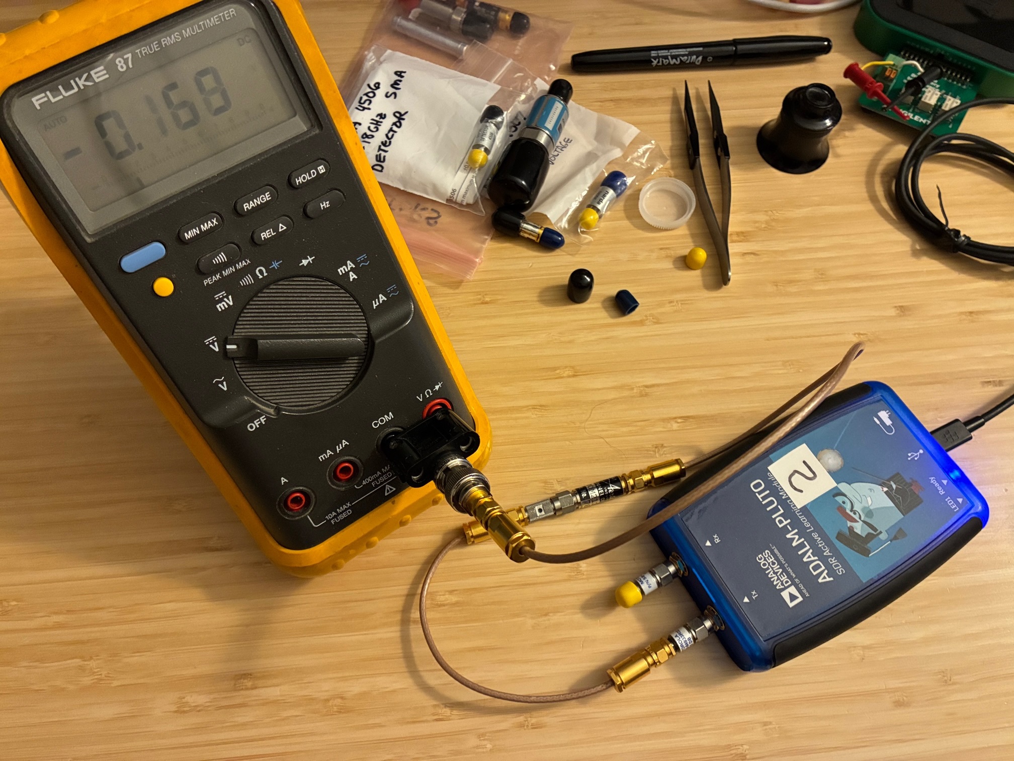
Turns out it is a negative detector and provides a nice range of output voltages when the 2 GHz applied signal is varied from approximately -30 to 0 dBm. It works! Next, let's look at the diode curve on the transistor tester.
Below was the measurement result. Looks like a "normal" diode curve (no tunnel jumping present as we're forward biased for this test).
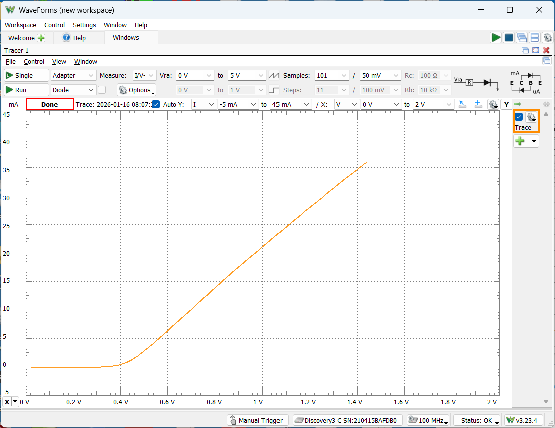
Wondering if we would see Esaki/tunnel diode effects? Short answer is no, I only tested in the forward direction (not reverse) and did not expect to see any jumps in the curve. Reviewing on-line sources for how to test tunnel diodes with curve tracers shows that a low source resistance is needed to zoom in and see the tunnel diode's reverse bias jumping characteristics. The low-cost Digilent Transistor Tester used today does not seem to offer changing the series resistor value as part of the test sequence. Will look into this more in the future. We might see that tunnel reverse biased jump someday!
Back to the test results, this detector's curve is different from the other AerTech detector measured as it yields around 22 mA at 1V. That's pretty interesting. All in all, today's tests reinforce that I have more to learn about characterization of RF diode detectors using this low-cost Digilent transistor tester. Clearly there is more to this than just measuring DC voltage output verses the applied RF signal level. More fun ahead!
See the next post for a quick check of their output DC levels with a varying RF input signal at 100 MHz.
All author photos taken with an iPhone 16e.