Troubleshooting a 33 cm RF LNA
I've had an Advanced Receiver Research (AAR) P900VDG GaAs Low Noise Amplifier (LNA) in the small RF modules box for a few years now and had the belief that it was not working properly. Let's take a few measurements to confirm that it is defective, or ideally, confirm that it works!
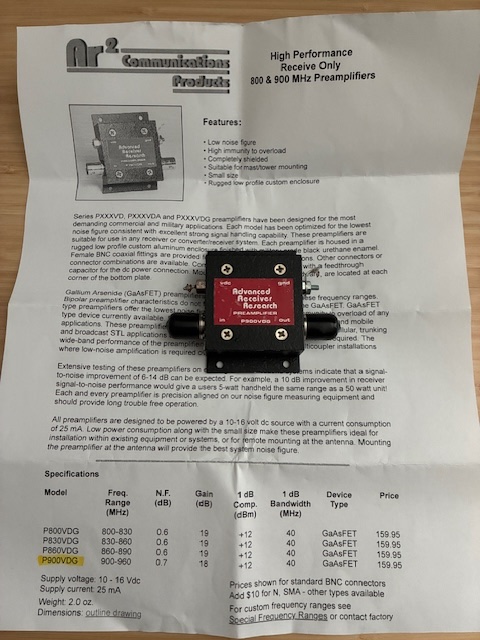
I was able to find a data sheet (but not a schematic) for the device. My LNA is marked on the back that it is tuned for 929.5 MHz. It should have around 18 dB of gain with a noise figure of 0.7 dB. The module runs off of 10-16 VDC and should draw 25 mA of current. Popping off the top cover shows no obvious signs of smoke!
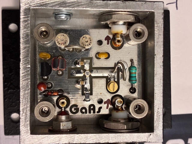
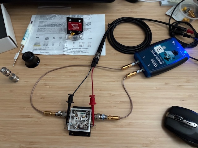
I added the two small black direction arrows on the PCB with my marker to ensure that I didn't mix up the input and output connections with the (marked) cover removed. The active device is marked with "Af".
Input/Output Impedance
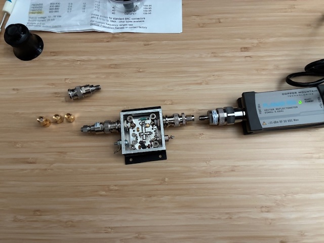
Lets look briefly at the input and output impedances with and without power applied using the CMT R54 vector impedance probe. (This probe was chosen specifically as it has a low power measurement level and it does not output other signals [subharmonics] as output by the NanoVNA-H4. See previous post here.) Getting calibrated and setup for the S11 measurement below.
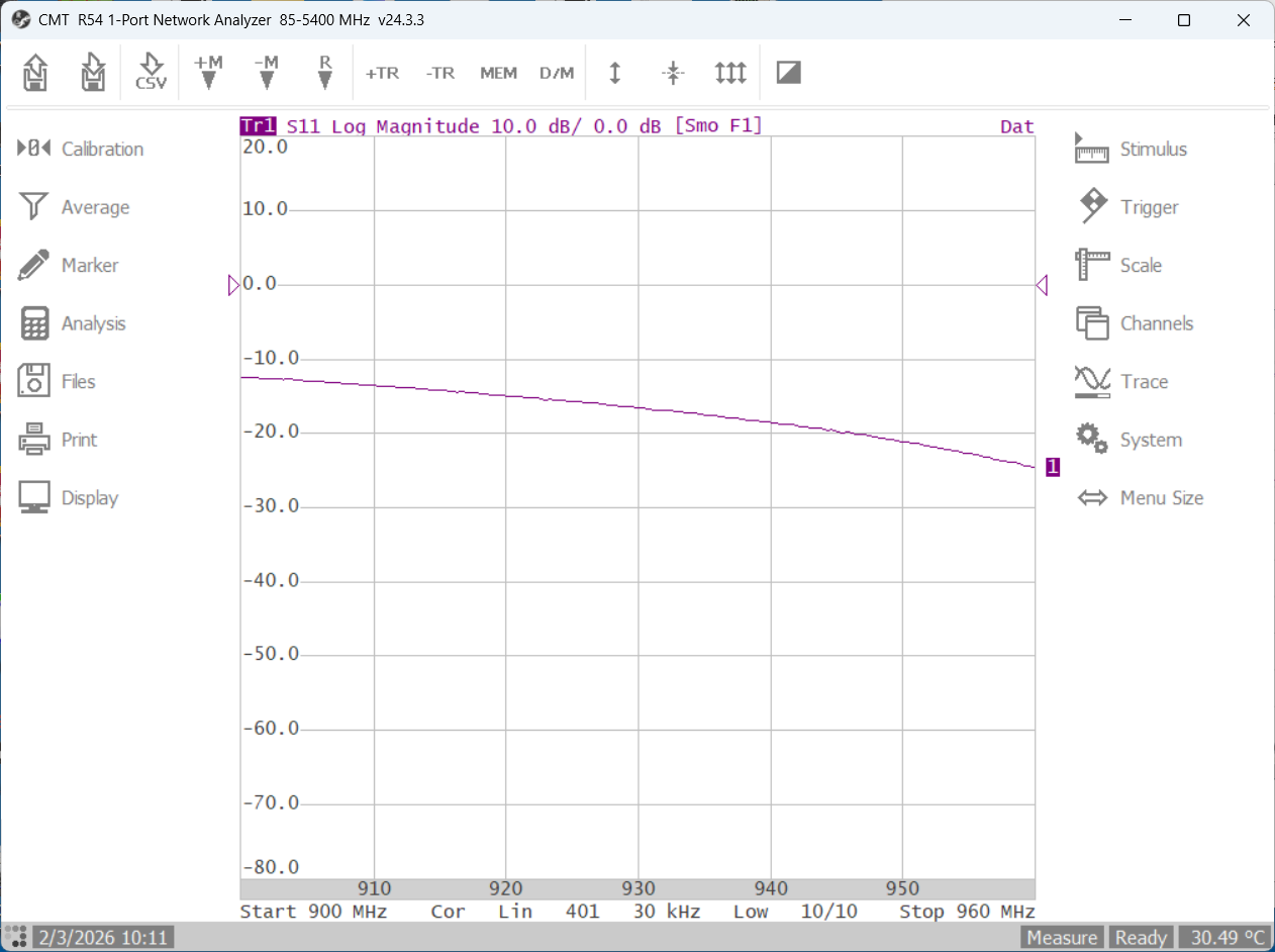
Input (S11) power off does not look terribly bad...
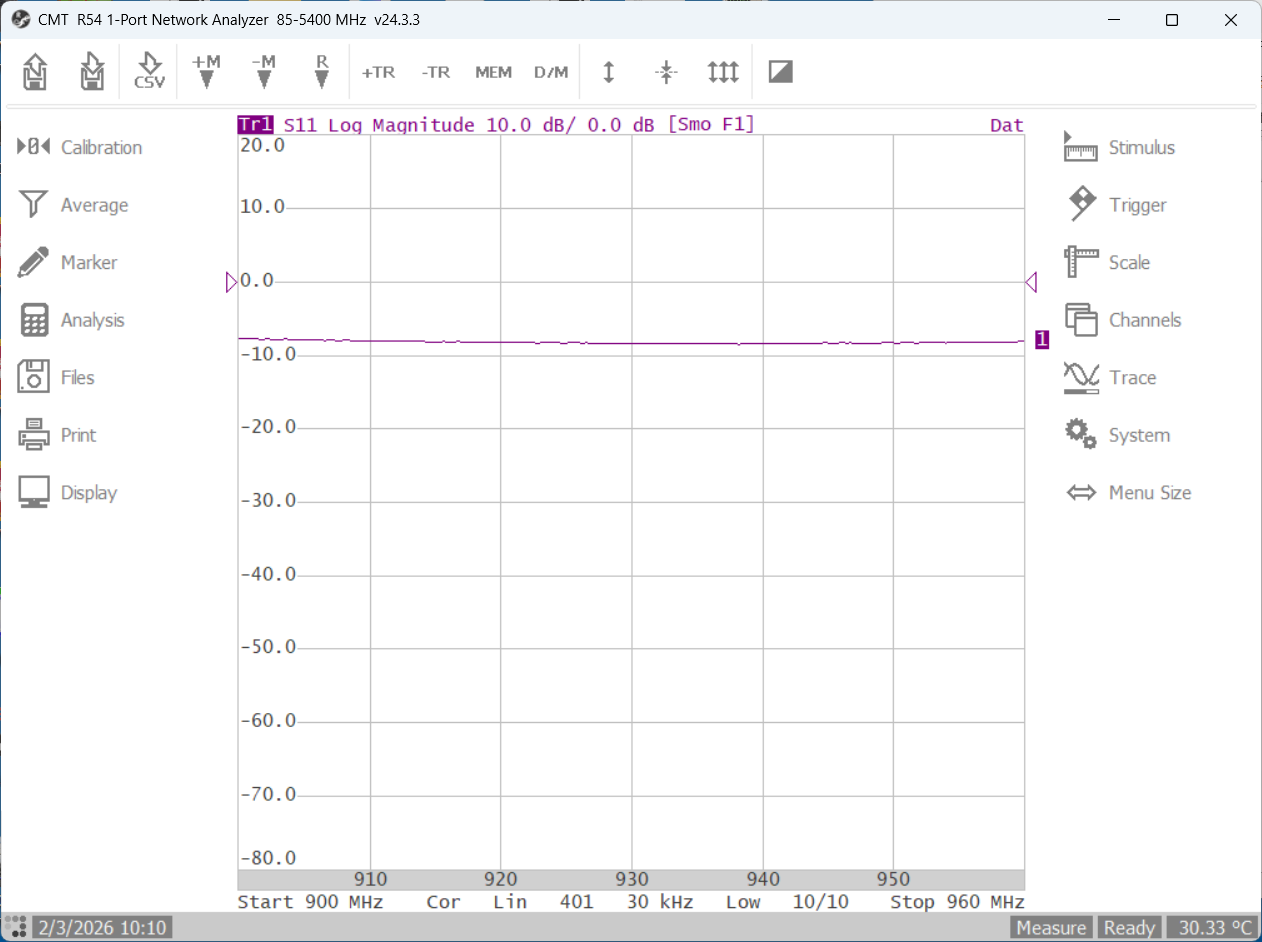
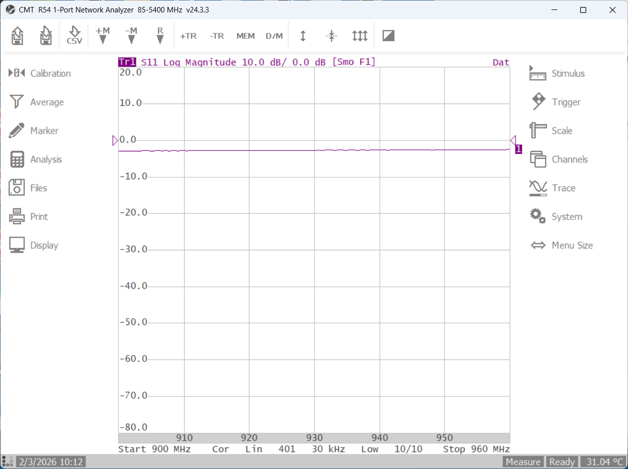
Applying 12V makes this get quite a bit better (and shows the input is tuned to the high end of the band).
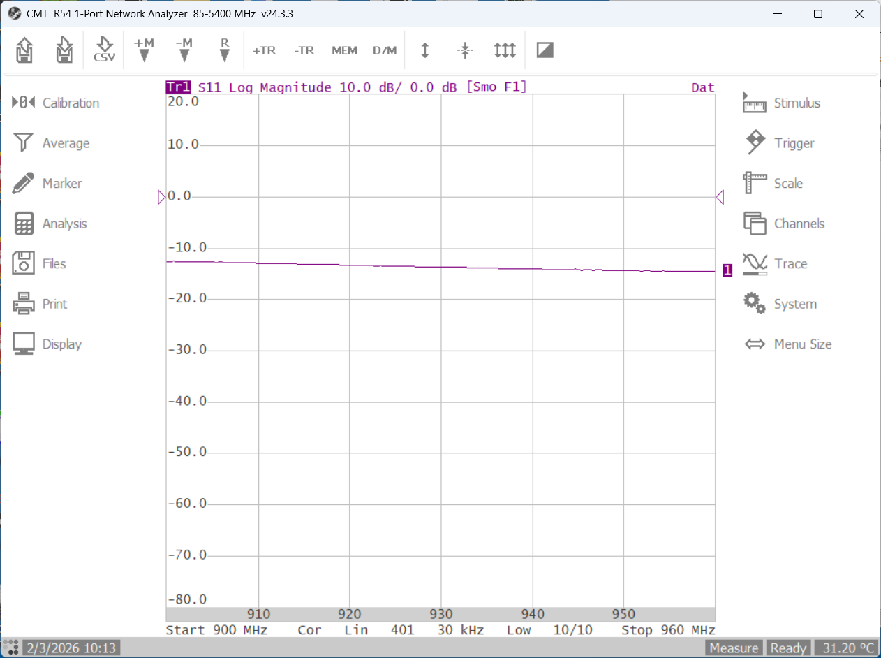
Output impedance (S22) with power off is below. Was expecting a little better, but will see how it changes when power is turned on.
Power is applied (below). That's better! Maybe this amplifier works? The input and output matches are reasonably good with power applied.
Gain Test
Due to the low signal levels this amplifier is designed for, it is not a good idea to just hook up the NanoVNA-H4 to it (see source power measurements here) without adding attenuators on the amplifier input side. My ADALM Pluto SDR controlled by SATSAGEN offers adjustable drive levels for a calibrated 2-port gain measurement. Let's use that...
Will it amplify? +12V power applied! (The measurement line should be above the zero line on the left scale...)
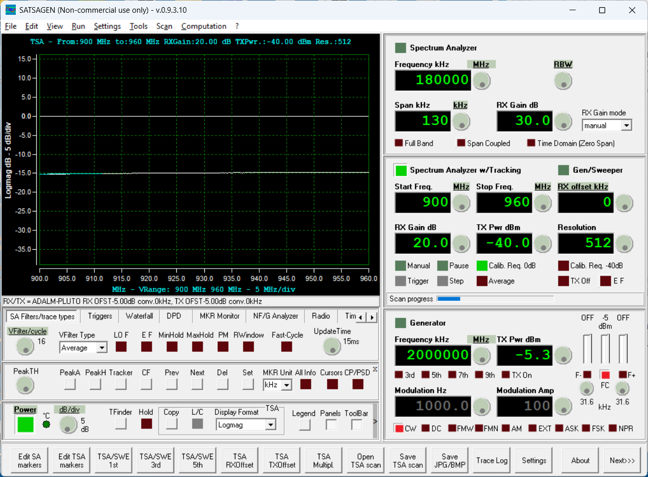
Sadly, not. The S21 (and S12) gain are both the same at -15 dB. This is not a working amplifier...
Biasing and Circuit Review
A fun next step is to look closer at the circuit and create a quick schematic for the RF amplifier.
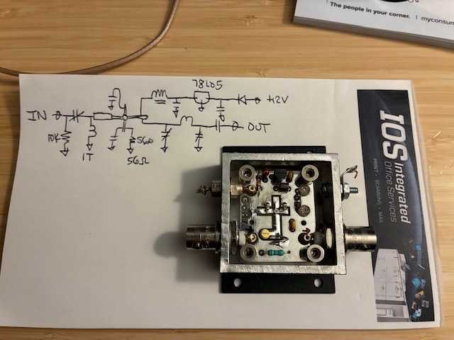
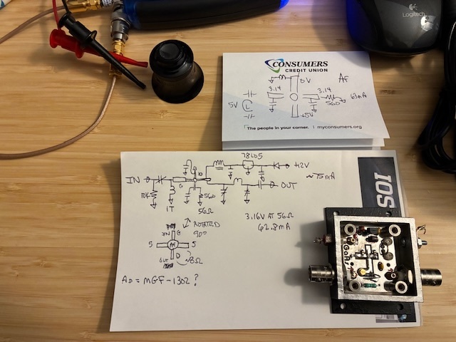
This is a classic N-Channel GaAs FET amplifier with 5 VDC at the drain, the gate DC grounded, and a resistor in the source current path (with the source RF bypassed with the two capacitors shown). The device self biases to move the source up in DC voltage, creating a negative voltage at the gate. The 10K resistor on the input jack provides limited protection against static build-up on the applied antenna connection. I measured 5V on the drain, 3.14V on the source pins. With a 56 ohm source resistor, this yields ~ 63 mA of source current, quite a bit more than the total 25 mA shown in the data sheet for the entire amplifier. (I estimated 10 mA'ish current drawn for the 7805 regulator and any unwanted leakage from the gate to ground.) A power-off ohm meter check shows around 8 ohms always present between the drain and the source. Suspecting a leaky/damaged device...
Made a few additional measurements with this final conclusion: the AAR amplifier appears to have a defective GaAs device.
A little internet searching yields this schematic for a lower frequency model of the ARR GaAs LNA. The schematic is similar, and mainly confirms the biasing circuit approach.

It is possible that my amplifier also uses the Mitsubishi MGF-1302 GaAs device, but not certain of that, as eBay part pictures show a marking of "Ad". Maybe just earlier versions of the same part?
Activity Summary: An Advanced Receiver Research (AAR) P900VDG GaAs low noise amplifier was examined, with input/output impedances measured, power applied, and throughput gain measured confirming that the device has negative 15 dB gain and draws ~ 75 mA of 12V current instead of the proper draw of ~ 25 mA. The GaAs device likely has an internal defect precluding proper operation. The module will be added to the qsl.net/n8dmt Extras page to see if anyone wants to take it on as project.
All author photos taken with an iPhone 16e.