RF Comb Generators Part 2
This is a follow on to the first posting on this topic (RF Comb Generators Part 1). Having completed the first two planned test steps, this post captures the remaining three steps:
- Connect test signal to input, setting input drive level per Note 2 (0 or +10 dBm), terminate output with spectrum monitor and power meter using splitter or coupler.
- Power up the device and see if it works!
- If it works, try varying the input frequency to see how far off from 640 MHz it operates without too much comb degradation.
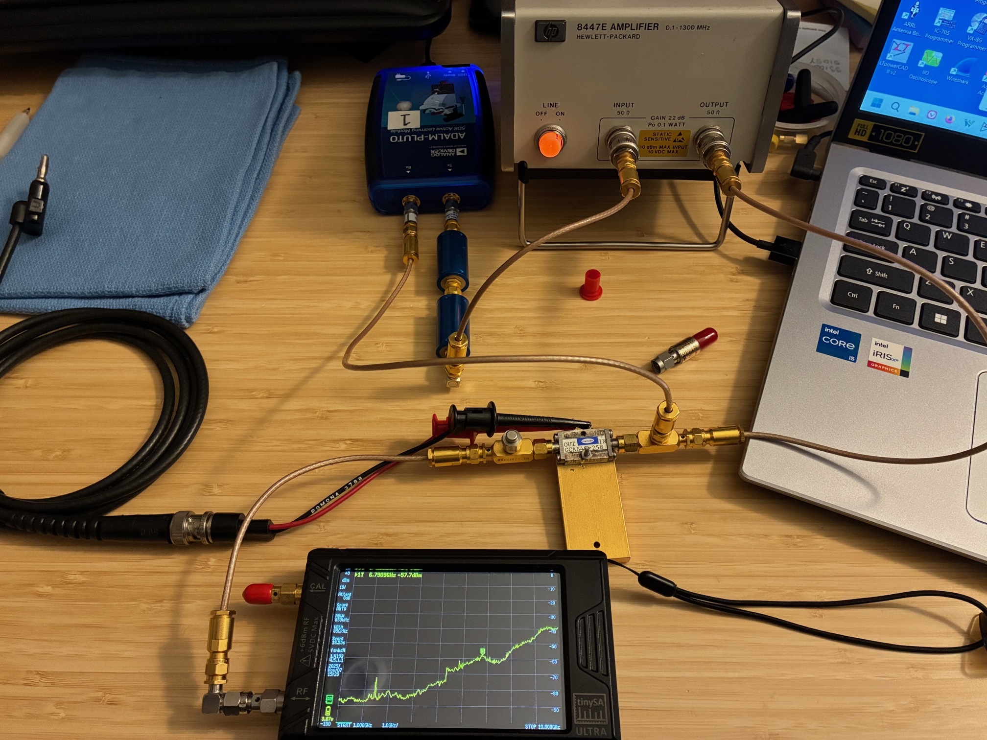
The 640 MHz input signal is generated using the setup described in the first post with the exception that two Omni-Spectra 203836-20 20 dB coupler are added on to the comb generator's input and output jacks. This allows monitoring of signals at these points in the system. For these initial tests, an RF cable is routed from the input-side coupler test port to the Pluto's RX port for monitoring by the spectrum analyzer function of SATSAGEN. The output monitoring point has a 50 ohm termination applied for now.
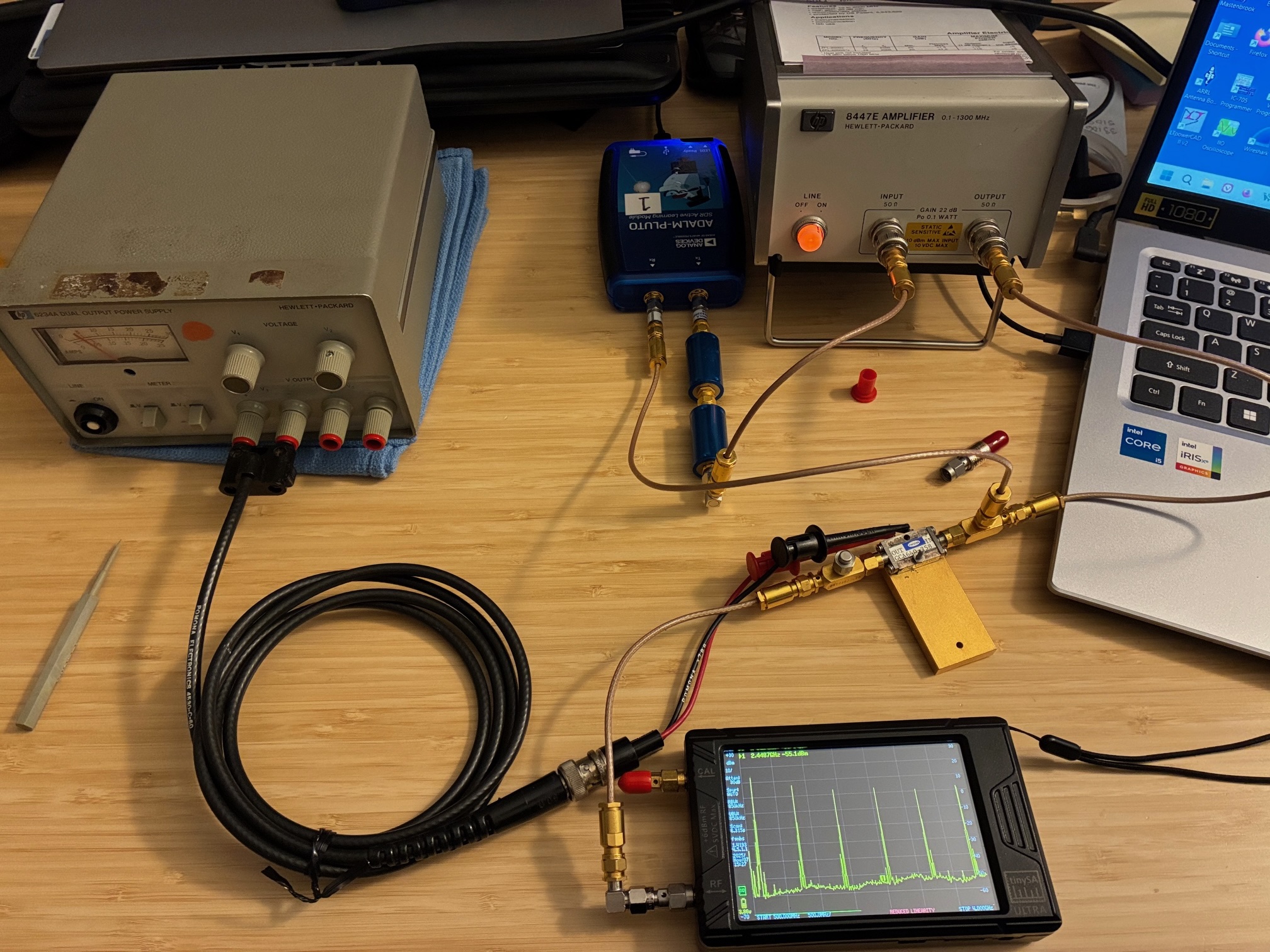
The setup shows the Pluto SDR signal source, the HP and LP filters, the ZFL-2000 RF amplifier (in the HP8447 case), a Omni-Spectra 20 dB sampler, the Herotek GCA640-258 comb generator with power leads connected, another Omni-Spectra 20 dB sampler (terminated), and a RF cable leading over to the TinySA-Ultra spectrum analyzer. DC power is off. (Ignore the TinySA-Ultra screen as it is set to an out of band upper frequency limit and the noise floor raises to a crazy level at those frequencies.)
With that (hooking up the +5 VDC supply and changing setting on the TinySA-Ultra), we're ready to power up the system and see if the comb generator works.
Power applied: Good news! The comb generator appears to work - outputting a nice series of harmonic signals into the TinySA-Ultra.
I quickly realized that the TinySA had pretty strong signals applied (> 0 dBm) and added a Narda 20 dB pad on its input connection. See below.
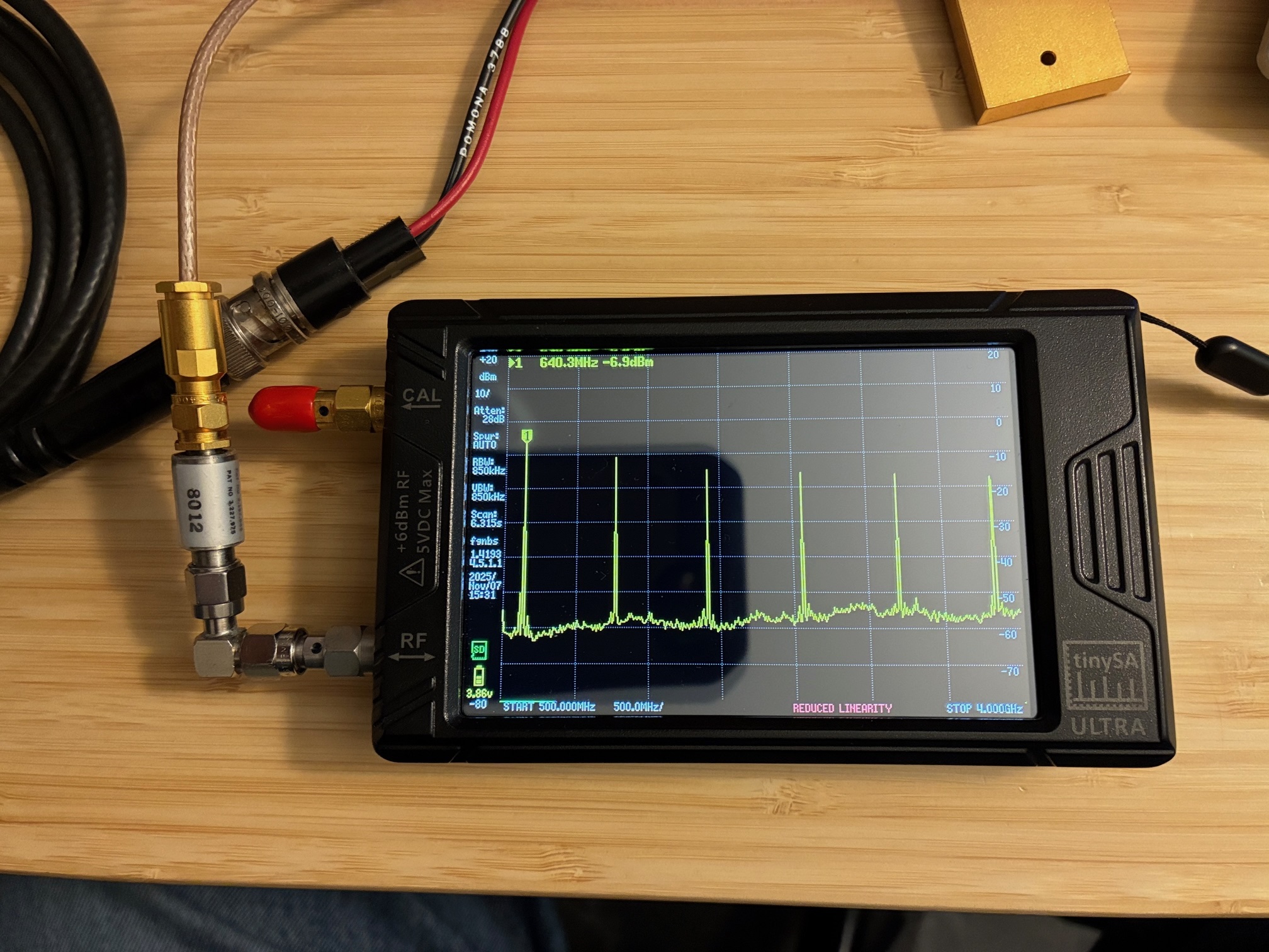
Below is a more readable screen capture / close-up of the TinySA's screen.
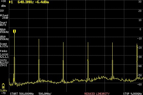
As a point of reference, those who look closely will see that there is a red text warning on the bottom of the screen (REDUCED LINEARITY). This appears anytime the upper frequency limit is over 800 MHz and is just a caution to the user to be careful when setting up and using amplitude measurement functions.
I increased the stop frequency a-bit to see how far up the combs went and came to the conclusion that the TinySA-Ultra just was not up to the task of seeing much above 6 GHz. (Can't expect too much from a $130 USD spectrum analyzer.) But the combs look pretty good up there too...
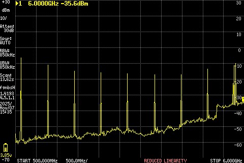
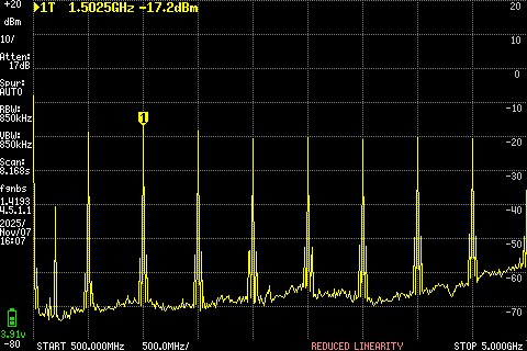
Next up was to change the input frequency both lower and higher than the nominal 640 MHz. For the chart below, the input was changed to 500 MHz and the combs still appear reasonably strong and level in amplitude.
Here is 800 MHz input. Still working, although likely running into the low pass filter I had on the output of the Pluto SDR. Might try this again in the future with a 1200 MHz LPF on the Pluto's output just to see if the comb generator works up to 1 GHz input. Having 1 GHz combs might be useful!

Overall, the input circuitry to the comb generator does not appear to be too tightly tuned to 640 MHz. This opens up options to operate the generator at other frequencies.
Happy to see a successful outcome to this series of tests. I'm not sure what I'll end up doing with this module, but am confident it will be used at some point in the future here in the home lab.
Achievement Unlocked: Add a comb generator to the lab's test capability!
A follow on posting will explore test and ham radio uses for a comb generator in a home RF lab. Here is a link to the third posting on this topic (DIY Comb Generator = $0.25 in parts).
All author photos captured with an iPhone 16e.