RF Comb Generators Part 3 (DIY Combs)
Following up testing of the Herotek GCA640-258 comb generator in Part 1 and Part 2, this post explores creating a super low cost comb generator using just a few components you may already have in your parts box.
While the hermetically sealed mil-spec Herotek module might have originally cost over $1,000 USD and covers up to around 18 GHz in its output spectrum, this level of performance is not likely to be needed in the typical home RF lab or ham radio scenario. Is it possible to create reasonable quality combs (and a comb on a specific frequency) using low cost components? Let's explore this in a third post on the topic.
A starting point for any comb generator is the input clock source. For the Herotek, I used a Pluto SDR controlled by SATSAGEN to set the 640 MHz input frequency. For a much lower cost clock source we can use an SI5351A clock generator to drive the comb generator. While there are many ways to setup and program a SI5351 chip, I used an EtherKit SI5351A evaluation board and controlled the clock/data programming using a Arduino UNO running a special sketch supplied by IU1KVL with user interface via the accompanying SATSAGEN Windows software package running on my ham radio Win11 laptop.
The above hardware and software configuration allows setting the clock zero (0) output frequency with a limited ability to set the output amplitude of the CLK-0 output.
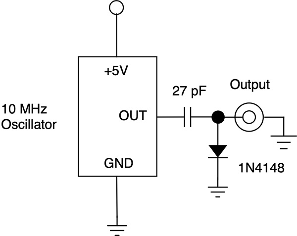
As part of learning about DIY comb generators, I had found a simple circuit (literally two passive components, a capacitor and a diode) on this InCompliance webpage. The author used a small fixed crystal controlled 10 MHz clock source, a series 27 pF capacitor, and a shunt-to-ground 1N4148 diode to create a RF comb with 5 MHz steps up to over 500 MHz.
My goal was to be able to select a specific frequency that a comb would fall on and thus needed an adjustable clock source. The SI5351A supports this goal of adjustable comb frequency.
I had questions about the clock drive level and frequency set function (accuracy and precision) under SATSAGEN control, but figured that just trying it out might answer these questions without too much fuss.
My component junk box is very limited (have moved multiple times in recent years) and consists of TI MyParts Kit and Analog Devices ADALP2000 parts kits along with a small parts stash that survived the huge purge before the first interstate move. Since I was only looking for a small value cap and a signal diode (1N914 or 1N4148), I dug out the kits and a small protoboard to work on.
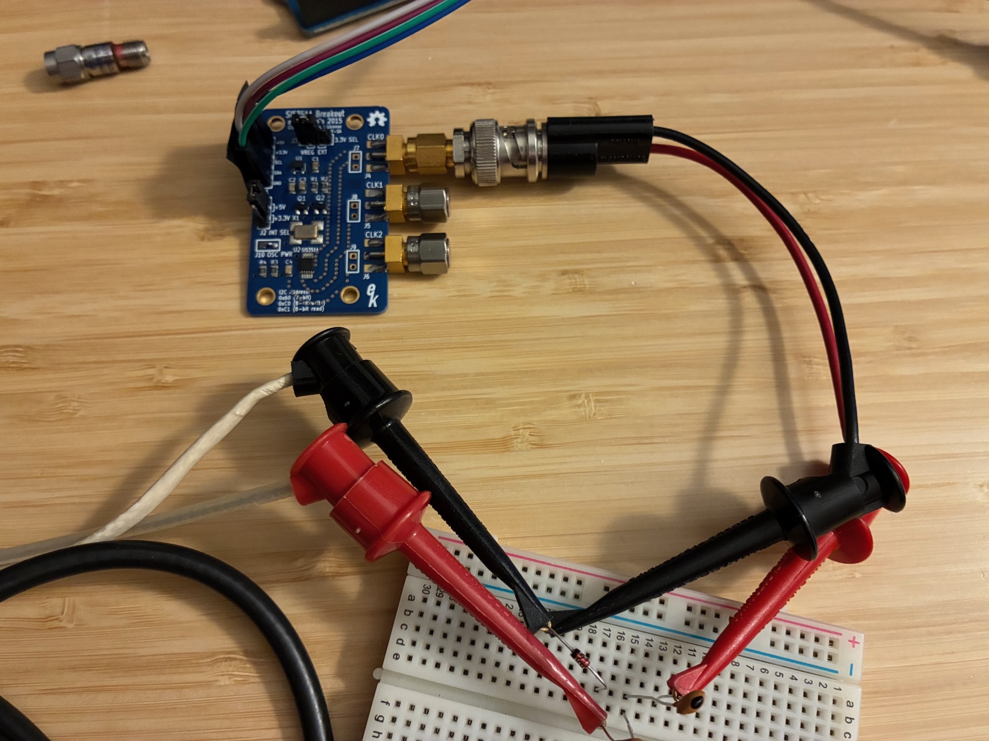
I found the 1N4148 diodes, but didn't have any smaller cap than 48 pF. Ended up using two of them in series, and it worked great! Here is the setup using clip on test leads (not worrying about parasitics at the moment).
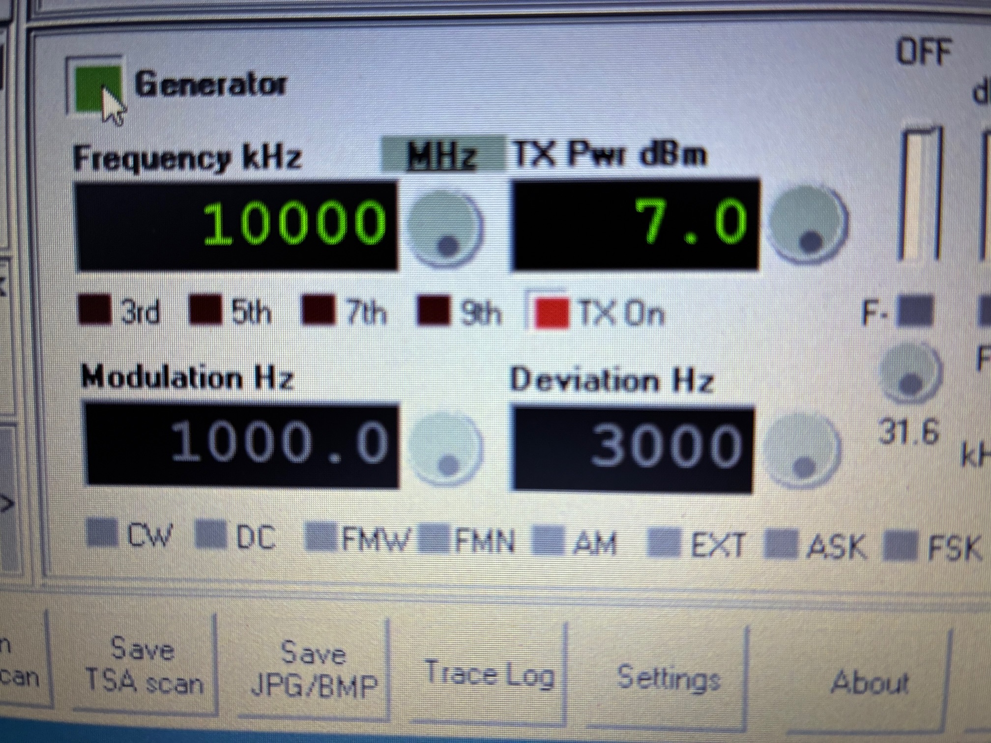
The SATSAGEN signal generator is controlling the SI5351A via the UNO interface.
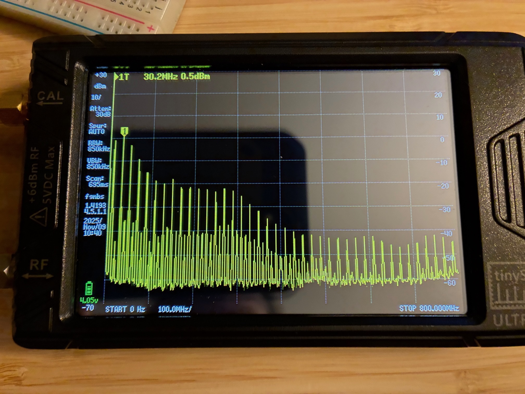
Below is a shot of the overall test setup, with UNO controlled SI5351A clock source, CLK-0 clip leaded to input series capacitor and output clip leads running from shunt 1N4148 diode to the TinySA-Ultra spectrum analyzer. A comb of RF signals is present on the SA display.
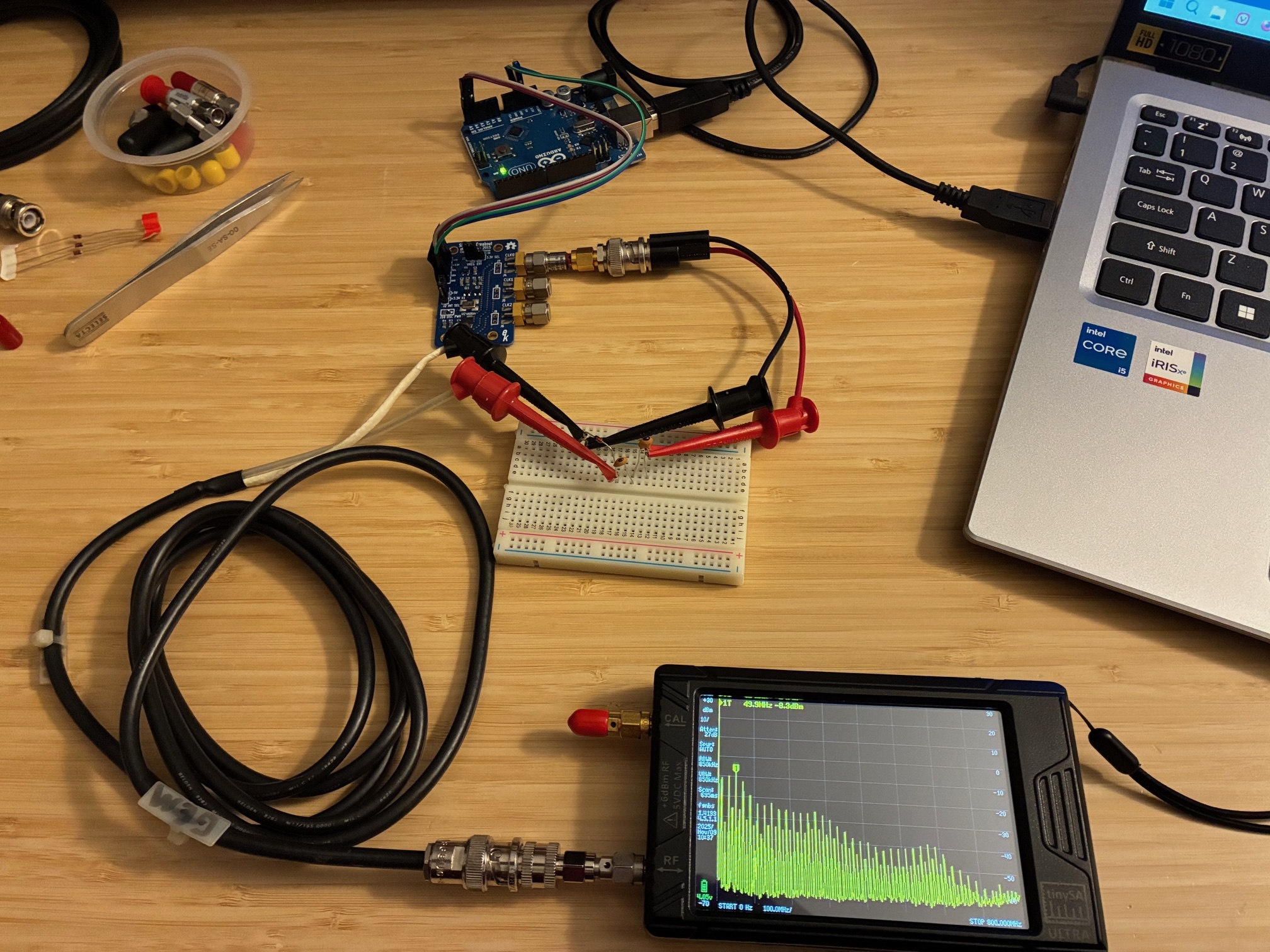
A closer shot of the TinySA-Ultra display shows a reasonable comb up to 800 MHz. Not too bad for around 25 cents of passive components!
Below is a close up of the clip leads to the parts on the protoboard...
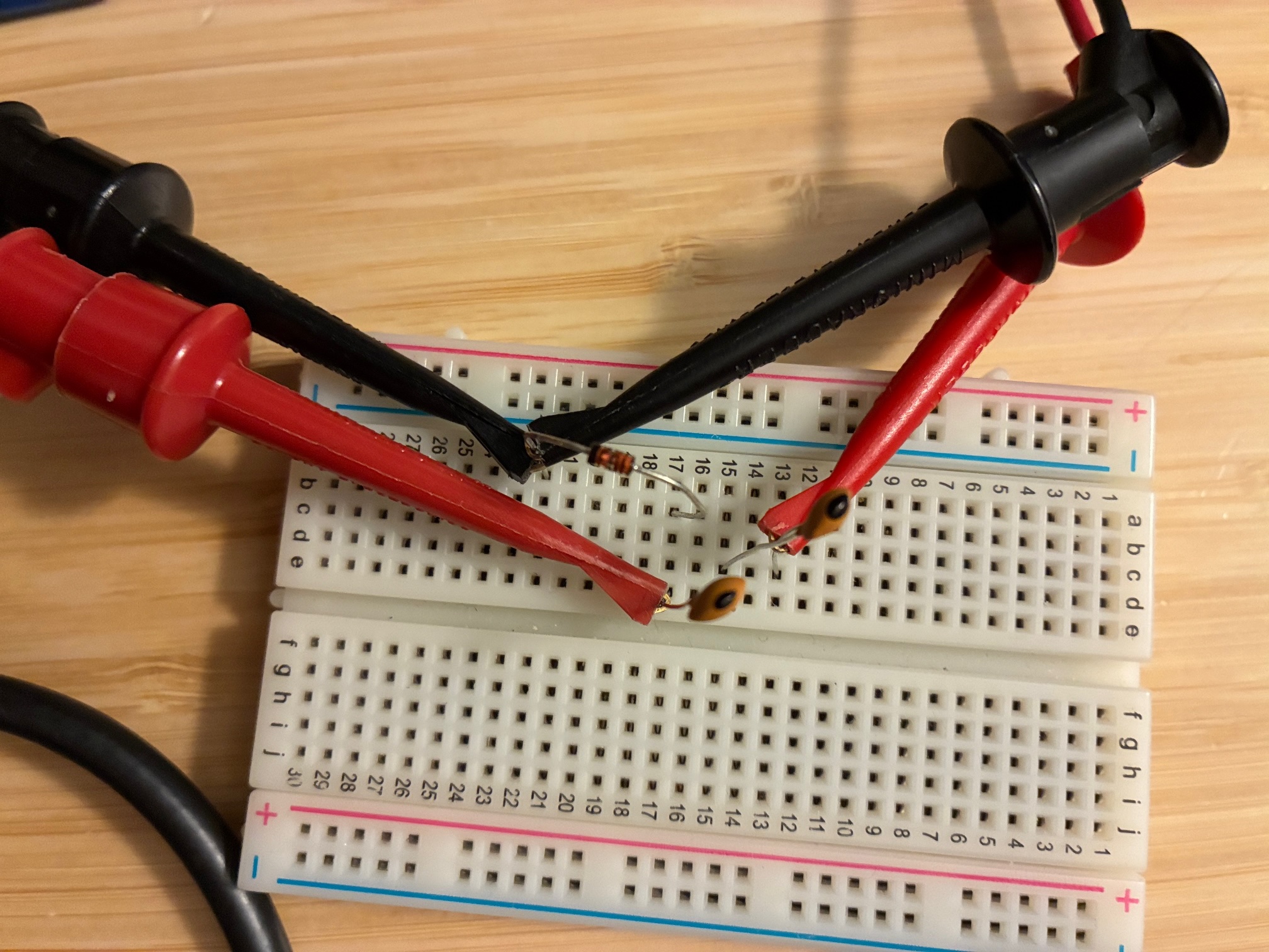
These three parts came out of the TI MyParts kit, so I thought I'd look for parts that might be dedicated to the project (and mounted on a small board for a more permanent solution). Digging in my small random remaining parts bin, I found a small signal diode (think it is a 1N914 or 1N4148) and a 15 nF capacitor). Would it work?
Swapping in the new capacitor and diode yielded this setup at the protoboard:
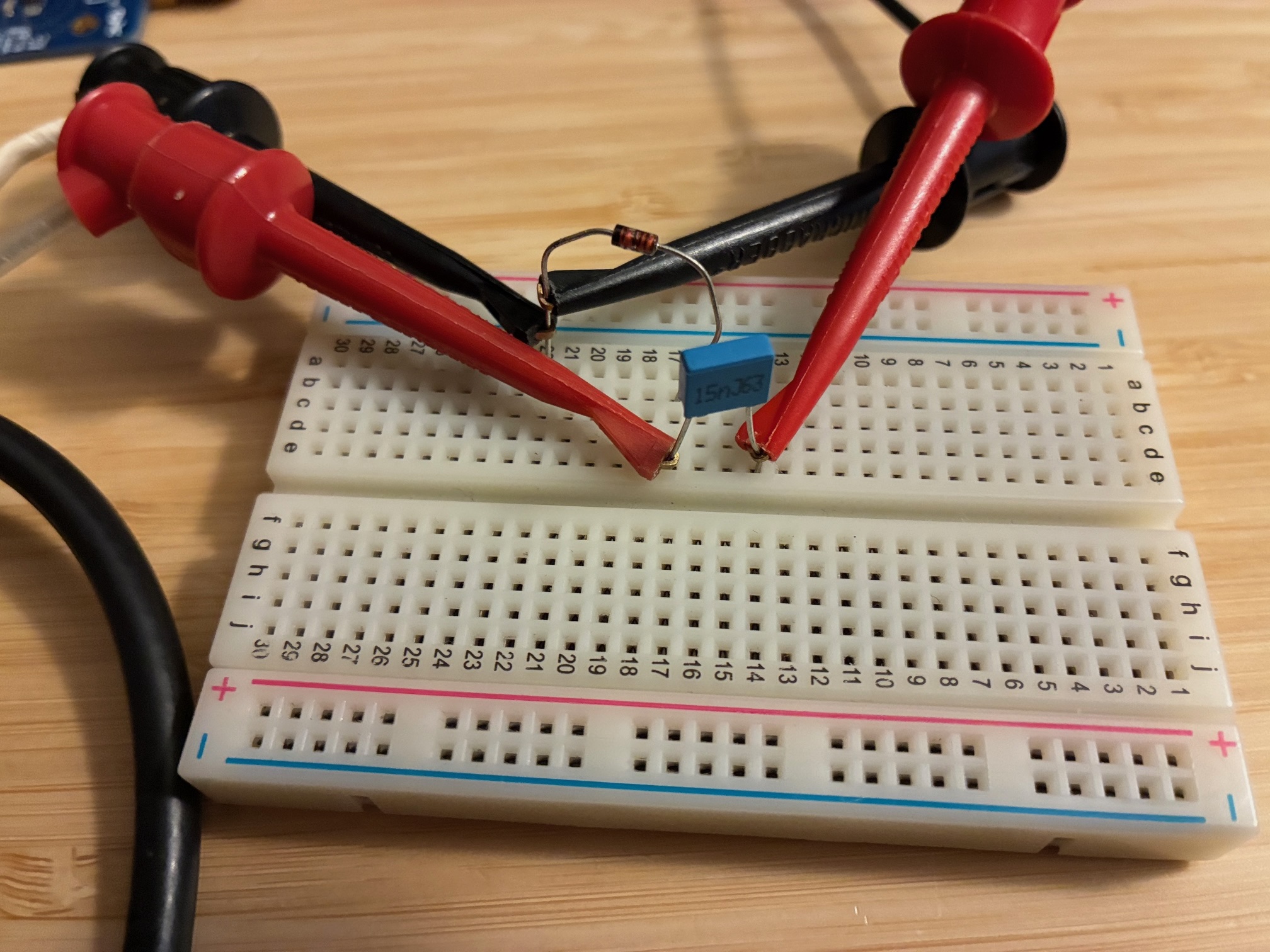
With the same clock source settings (10 MHz), the output comb is very reasonable.

Extending the upper frequency to 800 MHz shows the comb continues up to that point (and certainly beyond).
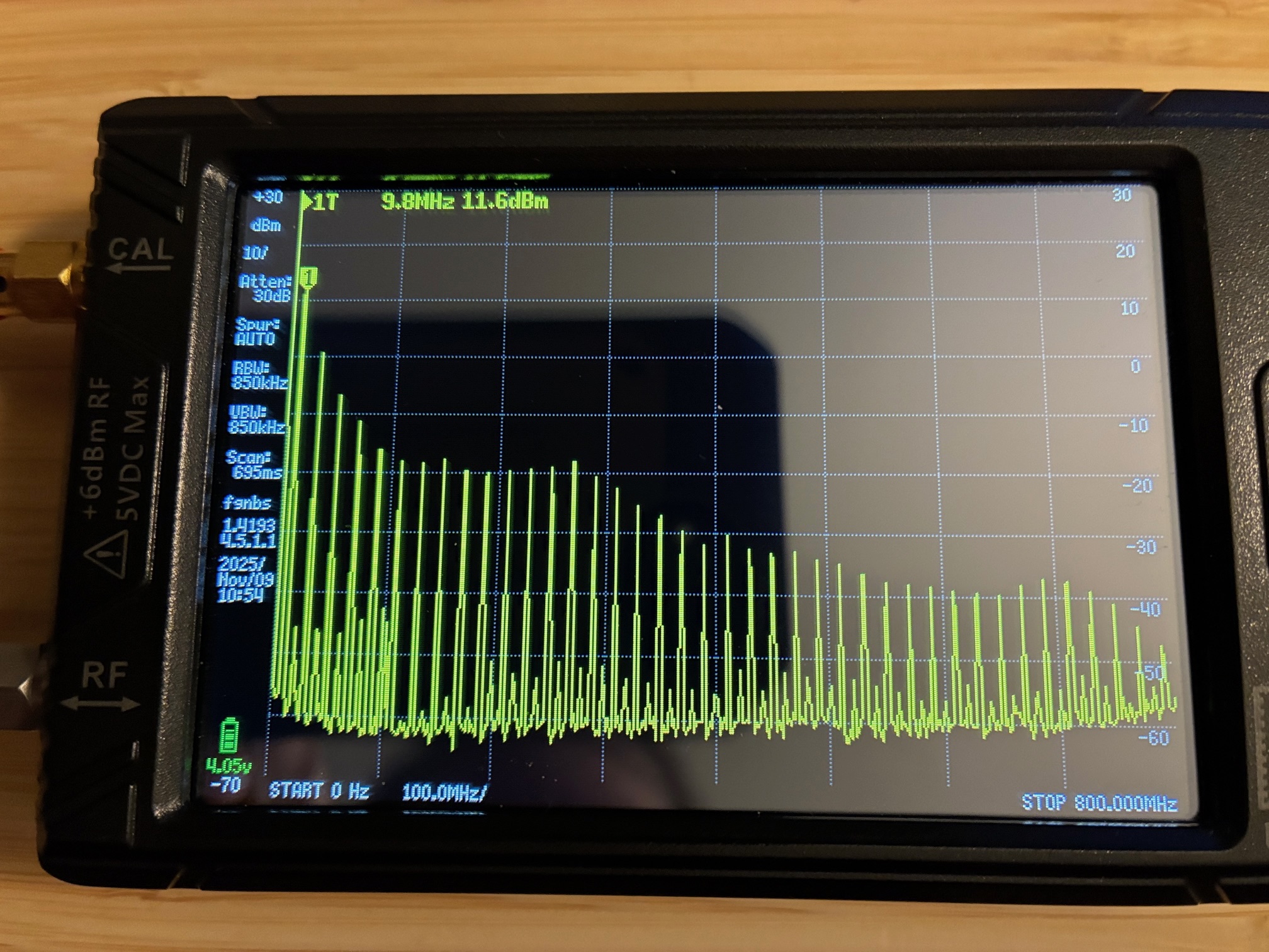
With this setup, it is possible to set a specific comb onto a specific frequency by adjusting the SI5351A CLK-0 output frequency via the SATSAGEN interface. I found it was relatively easy to set a comb to end up on 146.520 MHz using that method.
Achievement Unlocked: Low Cost Comb Generator ($0.25 USD if you already have an SI5351A evaluation board).
Next step is to build the comb circuit onto a small chunk of copper board with a pair of SMA jacks and the two passive components. Once constructed in a more permanent fashion, this new lower cost comb generator is likely to be used for lower frequency testing instead of the more expensive 500 MHz to 18 GHz Herotek module (as the GCA640 requires a 5VDC supply to be setup for use). Easy is good!
The final version was constructed onto a small board and tested. It works great! See the last posting on this topic at this link.
All author photos captured with an iPhone 16e.