RF Comb Generators Part 1
Comb generators are non-linear devices that create multiple harmonics of an input signal. Here is an introductory article on comb generators providing additional information on these devices.
I have been reading up on comb generators recently, having run across DIY comb generator kits and a few home built from basic electronic components. While pondering how to best approach this, I happened to run across a commercial comb generator module in my lab stock of miscellaneous electronics parts.
Many RF geeks tend to collect small connectorized modules - even if they don't know what it is or how they might use it someday. (They're small and don't take up much space, right?) This module was an example of someone offering "Want this? If so, it's yours." I am not sure how long it has been sitting around, but here it is. Let's explore what it does and see if it works!
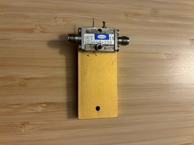
The RF module case appears to be silver plated and shows the effects of being exposed to finger oils for years without being cleaned. The RF connectors are stainless and would benefit from light cleaning inside and out. The DC and GND labels are likely epoxy ink marked - will need to be careful cleaning this later (if it works) to not accidentally remove them. The module is mounted to a heatsink using a single bolted connection.
This Herotek GCA640-258 module looks like an RF amplifier, with labeled input and output SMA jacks, along with a power input pin and a case/ground terminal. It's an amplifier, right? Sure - right up to the point where you search on the part number, don't find any amplifiers that match, and run across a web page with a data sheet describing a series of Herotek comb generators with similar part number structure.
The document titled: COMB (HARMONIC) GENERATORS WITH INTEGRAL PREAMPLIFIER includes a listing of features:
- Options for Input Drive of 0 dBm or +10 dBm
- Low Bias Voltage (+ 5V +/- 0.2V)
- Broadband Output Spectrum
- Hermetically Sealed Module
- Field Removable Connectors for Drop-In Assembly
- Custom Input Frequency Available from 10MHz to
10GHz - Drop-In Module Available (0.750” L x 0.248” W x
0.130” T)
Applications are listed as:
- Impulse Generator
- Frequency Multipliers
- Frequency Synthesizers
- Built-In-Self-Test Sources
Review of the part number indicates this is likely a custom 640 MHz input comb generator that runs off of +5 VDC, but it is not clear if this is a 0 dBm or a +10 dBm input drive model. The data sheet provides this information: Note 2: Bias voltage: +5 ± 0.2V. Current: 150mA nominal for “B” Model, 200mA for “A” Model.
Will need to check DC current to see if is a model A or B. Am guessing that the B model is for the +10 dBm input while the A model is for the 0 dBm input level (more RF gain needed to create the comb, so more DC current needed),
I plan to follow this test plan:
- Create a 640 MHz input test signal with selection between 0 and +10 dBm output level.
- Terminate input/output connections, apply current limited +5 VDC power, and measure DC input current.
- Connect test signal to input, setting input drive level per Note 2 (0 or +10 dBm), terminate output with spectrum monitor and power meter using splitter or coupler.
- Power up the device and see if it works!
- If it works, try varying the input frequency to see how far off from 640 MHz it operates without too much comb degradation.
1. Create 640 MHz Test Source
Have multiple options on generating this signal, including 1) using the Si5351 clock source multiplied up using Mini-Circuits frequency doubler modules, RF amps, and some high and low pass filters, 2) using the TinySA-Ultra in signal generator mode, or 3) use one of the ADALM Pluto SDR (with SATSAGEN controller), an RF amp, and a few Mini-Circuits filters to create a clean test signal.
I would like to use the TinySA-Ultra as a spectrum monitor (and can only use it in SA or sig-gen modes, but not both at once), so that option is out. The Si5351 approach would be fun to work through all the details, but is pretty complex to setup and execute. The Pluto SDR looks the easiest to setup and use.
Components used:
- Pluto SDR (#1) with SATSAGEN control
- Mini-Circuits SLP-800 RF low pass filter
- Mini-Circuits SHP-175 RF high pass filter
- HP 8447 (with ZFL-2000 replacement module) RF amplifier
- DIY stand alone RF power meter
- TinySA-Ultra spectrum analyzer
- MA/COM 2082-6173-10 DC-4 GHz 10 dB attenuator
- Misc RF cables and adapters
Assembling portions of the components yielded this test setup:
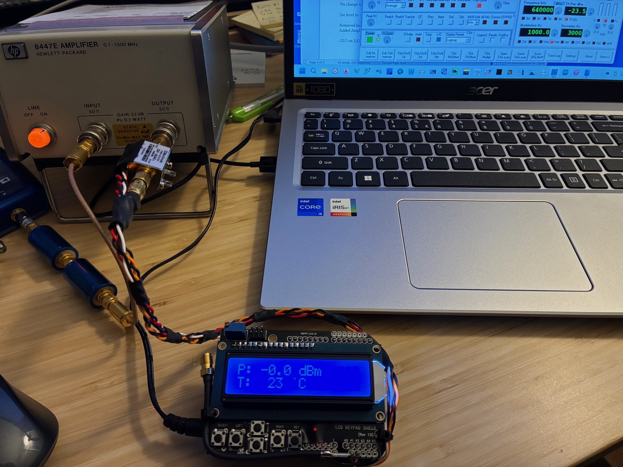
The Pluto's TX output passes through the 175 MHz high pass filter and the 800 MHz low pass filter, is amplified by the ZFL-2000 module (inside the HP8447 case) and then applied to the DIY RF power meter. Adjusting the Pluto output level via SATSAGEN controller (display in upper right of photo) yields 0 dBm at the output of the amplifier. This sets the levels to the lower input level of the comb generator module (A type). The amplifier supports testing for the B type version if needed by changing the SATSAGEN TX output level from -23 dBm up to -13 dBm if needed.
With levels set, we should look at the 640 MHz RF spectrum to ensure it is reasonably clean for a drive signal. Hooking up the TinySA-Ultra with a 10 dB pad on the input shows good spectral quality, with no visible harmonics or other spurious in the drive signal. The SATSAGEN level was adjusted up by 10 dB with corresponding TinySA-Ultra increase in observed signal level.
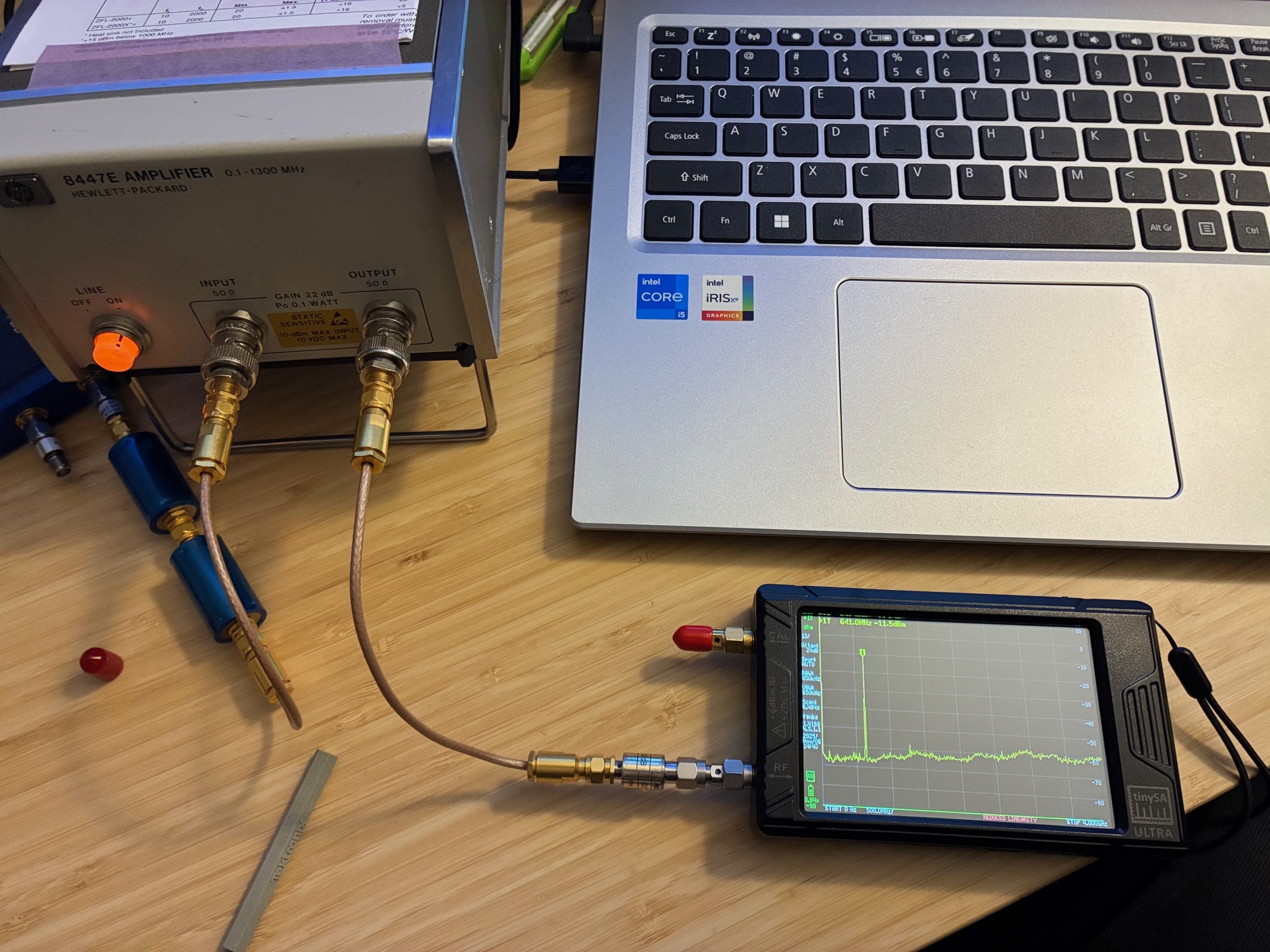
With this, the 640 MHz test signal is ready to go. Step 1 completed!
2. Measure 5 VDC Current
Connected a regulated 5 VDC power supply to the module and measured ~ 150 mA of current flow. Based on above assumptions, this is a B model with +10 dBm input RF level expected. (Plan to begin at 0 dBm and then ramp up to +10 input while monitoring the comb output levels.) Step 2 completed!
Conclusions
Achievement Unlocked: Input drive signal created at 640 MHz and module confirmed to draw +5 VDC power (not totally dead)!
The remaining steps (3 - 5) require more setup and I hope to get to them soon. For now, let's wrap up this Part 1 post. Will the module work? We're on the path to find out soon!
The second posting on this topic is available here.
All author photos captured with an iPhone 16e.